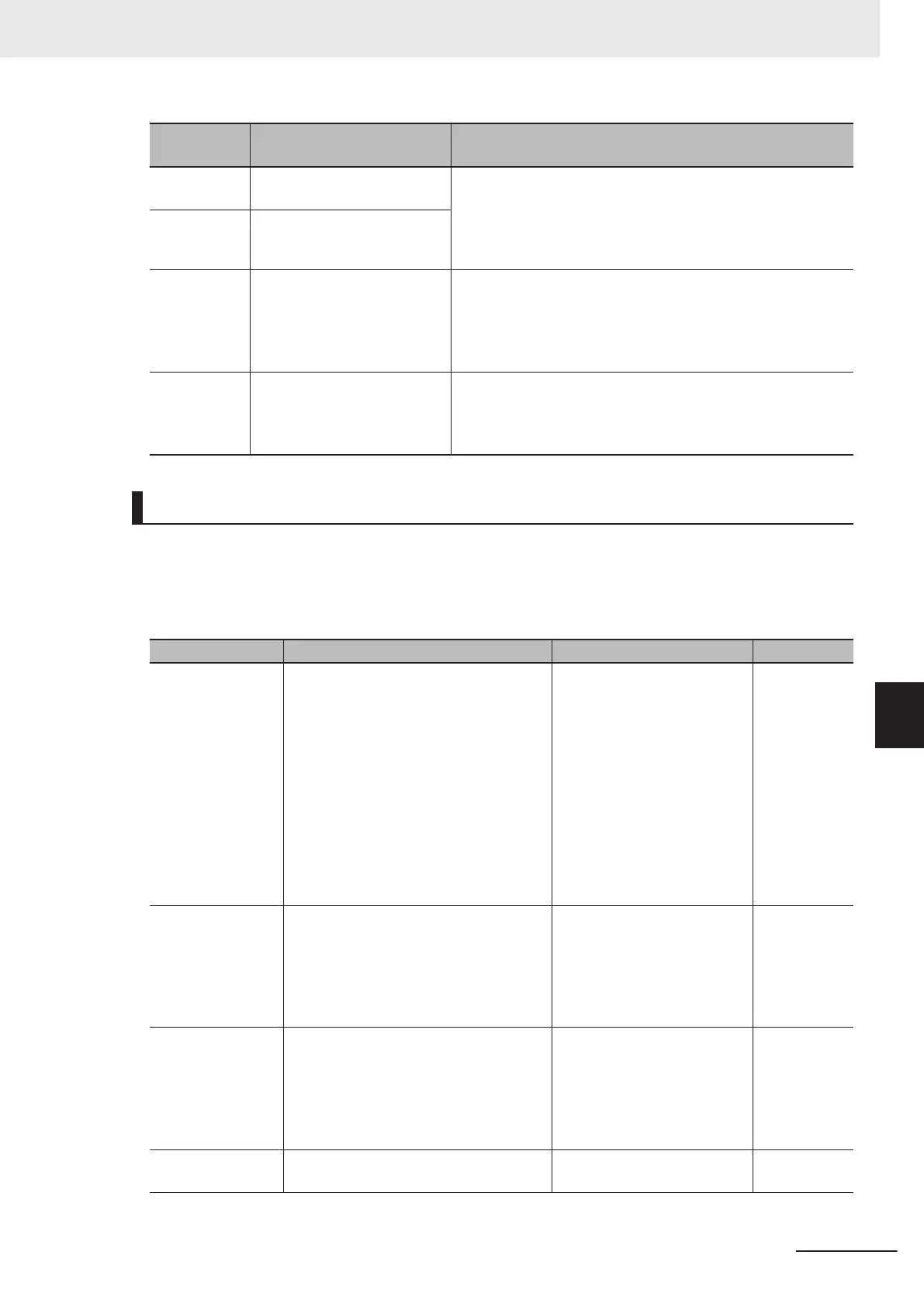
E61, E62,
E63 data
Function Description
17
Speed limit for forward rota-
tion
The analog input is used as the output frequency limit value.
Analog input 100% is equivalent to Maximum Output Frequen-
cy (F03/A01).
When using this function, the concomitant use of Over Speed
Detection Level (d35) is recommended.
18
Speed limit for reverse rota-
tion
20 Analog Input Monitor
By connecting analog signals to the inverter, the display coeffi-
cient can be used to convert and display analog signals as
temperature, pressure and other physical quantities via com-
munications.
100%/Full scale
21 PID feed forward
Enter the feedforward such as the temperature, pressure, etc.
in PID control. Set “1: Input terminal (AI1, AI2)” to PID Control
PID Feedforward Selection for Process Control (E121).
100%/Full scale
Using an Analog Input in Command System Parameters
• When using analog input terminals by the following functions, configure parameters for selecting the
commands of each function in addition to Input Terminal [AI1] Function Selection (E61), Input Termi-
nal [AI2] Function Selection (AII) (E62) and Input T
erminal [AI2] Function Selection (AIV) (E63).
When both are set to analog input, analog input signal is treated as a command.
Function Command setting E61, E62, E63 data Reference
Frequency com-
mand
1st Frequency Reference Selection
(F01)/2nd Frequency Reference Selec-
tion (C30) =
1: Analog Voltage Input (Input Terminal
[AI1])
2: Analog Current Input (Input T
erminal
[AI2] (AII))
3: Analog Voltage Input (Input Terminal
[AI1]) + Analog Current Input (Input Ter-
minal [AI2] (AII))
5: Analog Voltage Input (Input Terminal
[AI2] (AIV))
0: Frequency command page 5-27
Torque command
Torque Control Operate Selection (H18)
=
“3: Valid (Torque command: T
orque Ref-
erence)”
Torque Reference Selection (H332) =
“0: Input from analog (AI1, AI2) terminal”
10: Torque reference value page 6-31
Torque current
command
Torque Control Operate Selection (H18)
=
“2: Valid (Torque control: T
orque Current
Command)”
Torque Reference Selection (H332) =
“0: Input from analog (AI1, AI2) terminal”
11: Torque current command
value
page 6-31
Torque bias
Torque Bias Function Selection (H154) =
“2: Analog torque bias”
9: Torque bias page 6-33
7 Other Functions
7-37
M1 Series Standard Type User's Manual (I669)
7-3 Analog I/O Settings
7
7-3-1 Analog Input Function Selection

 Loading...