Input Terminal [AI1] Function Selection (E61), Input Terminal [AI2] Function Selection (AII) (E62) and Input
Terminal [AI2] Function Selection (AIV) (E63). When both are set to analog input, analog input signal is
treated as a command.
*2. Depending on unipolar or bipolar
, a bias value below 0 switches between enabled and disabled for Terminal
[AI2] (AII function) (Range / polarity selection).
For details, refer to 7-3-2 Analog Input Adjustment Function on page 7-38.
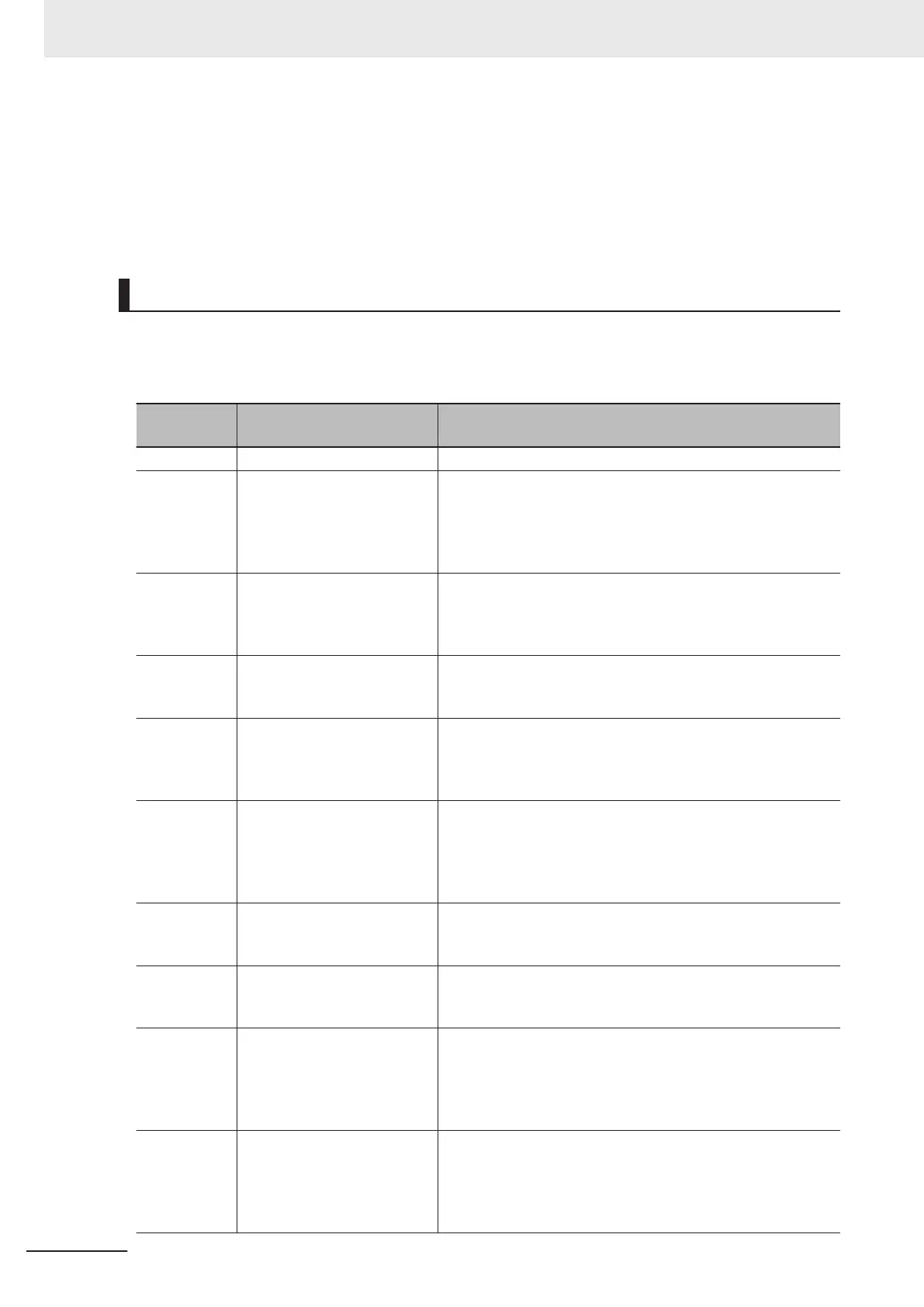
Analog Input Extended Function Selection (E61, E62, E63)
By setting Input Terminal [AI1] Function Selection (E61), Input Terminal [AI2] Function Selection (AII)
(E62) and Input Terminal [AI2] Function Selection (AIV) (E63), the following functions can be allocated
to each of the analog input terminals.
E61, E62,
E63 data
Function Description
0 None -
1 Auxiliary frequency setting 1
An auxiliary frequency input added to 1st Frequency Refer-
ence Selection (F01). Not added to other than the 1st frequen-
cy reference (such as the 2nd frequency reference, multi-step
frequency reference, etc.).
100%/Full scale
2 Auxiliary frequency setting 2
An auxiliary frequency input added to all frequency settings.
Added to frequency setting 1, frequency setting 2, multistep
frequency
, etc.
100%/Full scale
3 PID command
Enter the command source for the temperature, pressure, etc.
in PID control. It is also necessary to set PID Control PID
Command Selection (J02).
5
PID feedback
Enter the feedback for the temperature, pressure, etc. in PID
control. Set “0: Analog input” at PID Control Feedback Selec-
tion (E119).
100%/Full scale
6 Ratio setting
The ratio setting is used for the constant line speed control by
diameter calculation of the winding machine and the ratio oper-
ation of multiple units, and is therefore calculated as percent-
age in the last frequency reference.
100%/Full scale
7
Analog torque limiter
Used when the analog input is used as torque limit instead of
Torque Limit 1 (F40).
200%/Full scale
9 T
orque bias
The analog input is used as the torque bias value. Set “2: Ana-
log input” at Torque Bias Function Selection (H154).
200%/Full scale
10 T
orque command
During torque control, the analog input is used as the torque
command. Set “2: Torque current command input” or “3: Tor-
que command input” at T
orque Control Operate Selection
(H18) and “0: Analog input” at Torque Reference Selection
(H332).
11 Torque current command
During torque control, the analog input is used as the torque
current command. Set “2: Torque current command input” or
“3: Torque command input” at T
orque Control Operate Selec-
tion (H18) and “0: Analog input” at Torque Reference Selection
(H332).
7 Other Functions
7-36
M1 Series Standard Type User's Manual (I669)

 Loading...