Detection method
Individual out-
put terminal
*1
Monitor No.
(only for ST)
Remarks
Cooling fan
The time during which the cooling
fan is operating is counted. When
the operation time exceeds 87,000
hours (10 years), it is judged that
the end of life has reached.
WAF terminal
(241: W
AF)
Monitor No.
5_07 (Parame-
ter No. W68)
Can be reset by
Cumulative Run
Time of Cooling
Fan (H43).
*1. Select by output terminal function selection.
*2. With specifications and models shown below, the life is 61,000 hours (7 years) according to Load Mode Se-
lection (F80).
HND mode: A2022/037, A4022/040, AB002-022
ND mode: All models
7-8-15
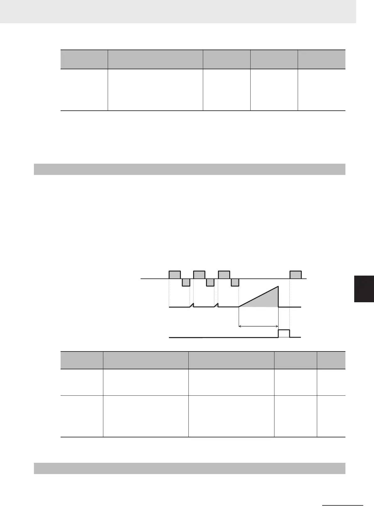
Communications Disconnection Detection Signal (NDc)
If communication is lost during Modbus communication, this signal is turned ON until the next data is
received.
Set the time until the reception timeout at RS-485 Communication T
imeout Time (y18).
The monitoring timer that detects the reception timeout starts under the following AND conditions.
•
The communication protocol setting is Modbus-RTU.
• “14: RS-485 communication” is set to Frequency Reference Selection (F01/C30) or “4: RS-485 com-
munication” is set to RUN Command Selection (F02/E102).
• RUN command ON
• Other than 0 is set to RS-485 Communication Timeout Time (y18).
(y18)
RS-485
Communication
Timeout Time
External controller
Inverter
Monitoring timer
Communication error
(NDc) output
Parameter
No.
Function name Data Default data Unit
y18
RS-485 Communication Time-
out T
ime
0: Not check of the time-out
(OFF)
0 s
1 to 60
E20, E21, E27
Output T
erminal [DO1] Function
Selection, Output Terminal
[DO2] Function Selection, Out-
put Terminal [ROA, ROB] Func-
tion Selection
209: NDc (Network error) - -
For details on communication, refer to Sec
tion 8 Communications Functions on page 8-1.
7-8-16
Starting Contact Signal (FR)
The starting contact signal is output for the duration that the “FW” terminal or “RV” terminal is being
input.
7 Other Functions
7-101
M1 Series Standard Type User's Manual (I669)
7-8 Functions Related to Protection, Warning and Various Output Signals
7
7-8-15 Communications Disconnection Detection Signal (NDc)
 Loading...


