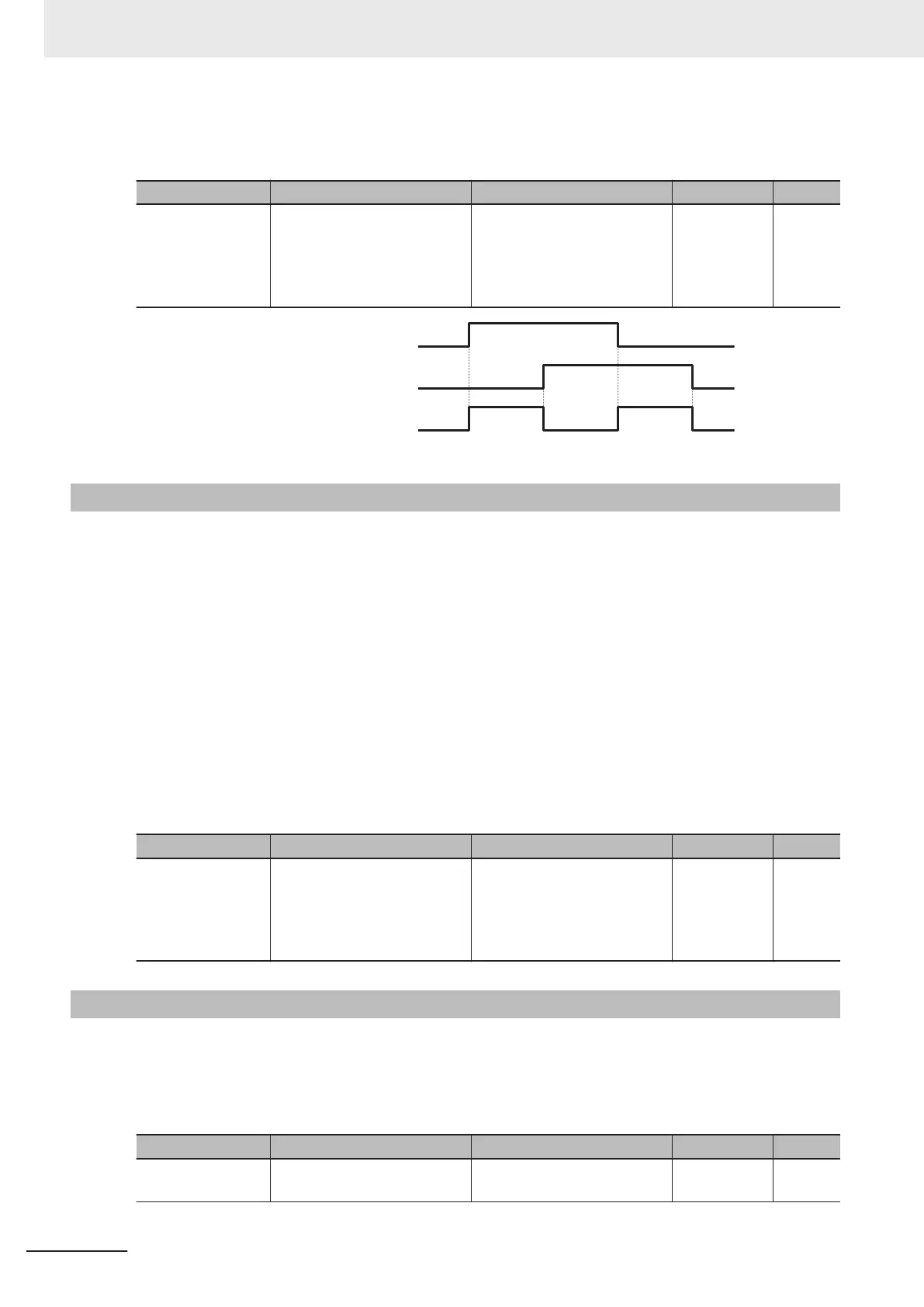
The inverter will stop if the FW and RV terminals are input simultaneously, and the FR terminal (187:
Starting contact signal) turns OFF.
Parameter No. Function name Data Default data Unit
E20, E21, E27
Output Terminal [DO1] Func-
tion Selection, Output Termi-
nal [DO2] Function Selection,
Output Terminal [ROA, ROB]
Function Selection
187: FR (Starting contact sig-
nal)
- -
Forward command (FW)
Reverse command (R
V)
Starting contact (FR) output
7-8-17
Cooling Fin Overheat Warning (OHF)
This function monitors the temperature of the cooling fin of the inverter and turns the cooling fin over-
heat warning signal ON/OFF according to the conditions below.
• When the cooling fin overheat warning signal is OFF
The cooling fin overheat warning signal turns ON when the cooling fin temperature is overheat trip
temperature - 5°C or above.
•
When the cooling fin overheat warning signal is ON
The cooling fin overheat warning signal turns OFF when the cooling fin temperature is overheat trip
temperature - 8°C or below.
• When the cooling fin temperature is the overheat trip temperature or above, cooling fin overheat oc-
curs (alarm code: OH1).
Parameter No. Function name Data Default data Unit
E20, E21, E27
Output Terminal [DO1] Func-
tion Selection, Output T
ermi-
nal [DO2] Function Selection,
Output T
erminal [ROA, ROB]
Function Selection
28: OHF (Fin overheat warn-
ing)
- -
7-8-18
Low Current Signal (LOC)
This Light load detection signal (LOC) is output when the output current falls to or below 1st Overload
Early Warning Detection Level (E37).
At Low Current Detection Condition Selection (LOC) (E184), select whether to have the inverter output
this signal constantly during run or only during constant speed operation.
Parameter No. Function name Data Default data Unit
E37
1st Overload Early Warning
Detection Level
0.00: Disable
0.01 to 3000 A
21.00 A
7 Other Functions
7-102
M1 Series Standard Type User's Manual (I669)

 Loading...


