Parameter No. Function name Data Default data Unit
E38
1st Overload Early Warning
Detection Timer / Low Current
detection level (OL, LOC)
0.01 to 600.00 10.00 s
E184
Low Current Detection Condi-
tion Selection (LOC)
0: Output during acceleration/
deceleration and constant-
speed operation
1: Output only during con-
stant-speed operation
*1
- -
E20, E21, E27
Output T
erminal [DO1] Func-
tion Selection, Output Termi-
nal [DO2] Function Selection,
Output Terminal [ROA, ROB]
Function Selection
41: LOC (Light load detection
signal)
- -
Related function
Output T
erminal [DO1] ON Delay Time (H309),
Output Terminal [DO2] ON Delay Time (H31
1),
Output Terminal [ROA, ROB] ON Delay Time (H313),
Output Terminal[DO1] OFF Delay Time (H310),
Output Terminal[DO2] OFF Delay Time (H312),
Output Terminal [ROA, ROB] OFF Delay Time (H314)
*1. If analog input (F01/C30 = 1, 2, 3, 5) is selected for 1st Frequency Reference Selection (F01)/2nd Frequen-
cy Reference Selection (C30), the signal may not be judged as a constant speed depending on the sam-
pling condition. In this case, set E184 = 0 (Output during acceleration/deceleration and constant-speed op-
eration), or increase the value set at Input Terminal [AI1] Filter (C33).
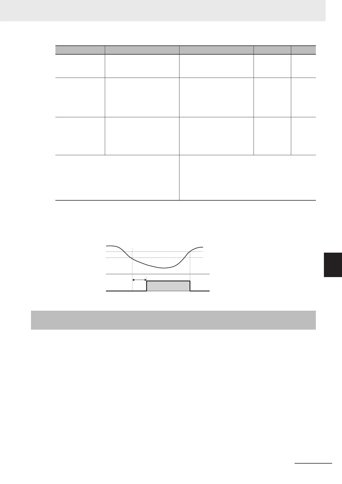
Detection level + Inverter rated current + 5%
Detection level
Output current
LOC
ON
Timer
7-8-19
Window Comparator/Disconnection Detection (AI1Dc/AIIDc/
AIVDc)
The window comparator signal is output when the input value of the analog input terminals [AI1], [AI2]
(AII) and [AI2] (AIV) is between the upper and lower limit level of the window comparator. It is useful
for monitoring the analog input at a level to detect disconnection or other faults.
Set the detection upper limit level by Analog Input [AI1] Detection Upper Limit Level (E157)/Analog In-
put [AI2] Detection Upper Limit Level (E160), detection lower limit level by Analog Input [AI1] Detection
Lower Limit Level (E158)/Analog Input [AI2] Detection Lower Limit Level (E161) and detection hystere-
sis width by Analog Input [AI1] Level Detection Hysteresis Width (E159)/Analog Input [AI2] Level De-
tection Hysteresis Width (E162) for each of analog input terminals [AI1] and [AI2] (AII/AIV).
Analog operation level at AI1Dc/AIIDc/AIVDc output can be set to any value by Analog Operation Lev-
el at [AI1] Disconnection (E163)/Analog Operation Level at [AI2] Disconnection (E164). When set to
999, the analog input value will be used as is.
7 Other Functions
7-103
M1 Series Standard Type User's Manual (I669)
7-8 Functions Related to Protection, Warning and Various Output Signals
7
7-8-19 Window Comparator/Disconnection Detection (AI1Dc/AIIDc/AIVDc)

 Loading...


