No. Field name Example (hex) Remarks
7 CRC-16 (LSB) 3F
*1. Broadcasting cannot be performed.
*2. Data as much as the number of data bytes will be transferred. The MSB (the first received data) has the
smallest coil address.
The data received in a response shows the status for coils 0003 to 000F hex. Therefore, the re-
ceived data “805 hex=1000 0000 0101” can be read, with the status for coil 0003 hex as the LSB,
as described in “Response” on the previous page.
The received data is always transferred in 1-byte (8 bits) format. Bits that lack data are transferred
as 0.
If the Read Coil Status function is not executed normally, refer to 8-5-9 Exception Response on
page 8-20.
(Ex-
am-
ple)
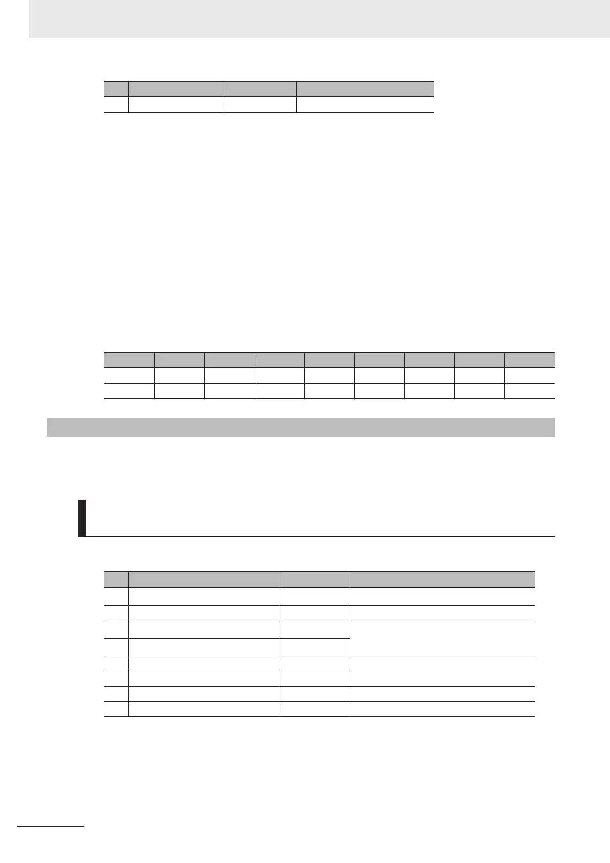
When the status of 16 coils starting from coil number 0001 hex is read, the order of data is as shown
below. Data 1 is the initial byte data to be sent.
bit 7 bit 6 bit 5 bit 4 bit 3 bit 2 bit 1 bit 0
Data 1 0008 hex 0007 hex 0006 hex 0005 hex 0004 hex 0003 hex 0002 hex 0001 hex
Data 2 0010 hex 000F hex 000E hex 000D hex 000C hex 000B hex 000A hex 0009 hex
8-5-2
Read from Holding Register [03 hex]
Reads the contents of only the specified number of consecutive holding registers from the specified
holding register address.
Example) Reading Latest Trip Data (0012 hex to 001B hex) from In-
verter with Slave Address 1
Query
No. Field name Example (hex) Remarks
1
Slave address
*1
01
2 Function code 03
3
Register start address (MSB)
*2
00
(Register address) = (Register number) − 1
4
Register start address (LSB)
*2
11
5 Number of holding registers (MSB) 00 10 registers
6 Number of holding registers (LSB) 0A
7 CRC-16 (MSB) C4
8 CRC-16 (LSB) 08
*1. Broadcasting cannot be performed.
*2. Note that the holding register start address is 0011 hex, which is 1 less than the register number 0012
hex: Register address = Register number - 1.
8 Communications Functions
8-12
M1 Series Standard Type User's Manual (I669)

 Loading...


