Response
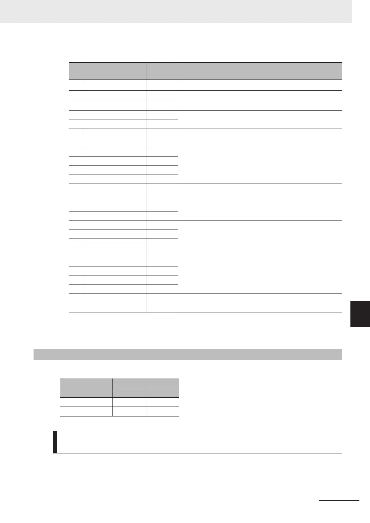
No. Field name
Example
(hex)
Remarks
1
Slave address
*1
01
2 Function code 03
3
Number of data bytes
*2
14
4 Register data 1 (MSB) 00 0001 hex → 01 dec → OC1 Overcurrent protection (during ac-
celeration)
5 Register data 1 (LSB) 01
6 Register data 2 (MSB) 02 201 hex → 1000000001 bin → FW: During forward operation,
ACC: During acceleration
7 Register data 2 (LSB) 01
8 Register data 3 (MSB) 00 4D2 hex → 1234 dec → 12.34 [Hz] (Frequency)
9 Register data 3 (LSB) 00
10 Register data 4 (MSB) 04
11 Register data 4 (LSB) D2
12 Register data 5 (MSB) 01 012C hex → 300 dec → 3.00 [A] (Current)
13 Register data 5 (LSB) 2C
14 Register data 6 (MSB) 0B 0B18 hex → 2840 dec → 284.0 [V] (DC voltage)
15 Register data 6 (LSB) 18
16 Register data 7 (MSB) 00 A hex → 10 dec → 10 [hex] (Cumulative running time)
17 Register data 7 (LSB) 00
18 Register data 8 (MSB) 00
19 Register data 8 (LSB) 0A
20 Register data 9 (MSB) 00 A hex → 10 dec → 10 [hex] (Cumulative operation time)
21 Register data 9 (LSB) 00
22 Register data 10 (MSB) 00
23 Register data 10 (LSB) 0A
24 CRC-16 (MSB) F9
25 CRC-16 (LSB) 14
*1. Broadcasting cannot be performed.
*2. Data as much as the number of data bytes will be transferred. In this example, the inverter sends back
data from 10 holding registers, which is 20 (14 hex) bytes.
8-5-3
Write to Coil [05 hex]
Writes to a single coil. The coil status changes as shown in the table below.
Data
Coil status
OFF to ON ON to OFF
Written data (MSB) FF hex 00 hex
Written data (LSB) 00 hex 00 hex
Example) Issuing Forward Run Command to Inverter with Slave
Address 1
You need to set the Run command selection to communications (F02/E102=4).
The coil number for the forward run command is 0001.
8 Communications Functions
8-13
M1 Series Standard Type User's Manual (I669)
8-5 Explanation of Each Function Code
8
8-5-3 Write to Coil [05 hex]

 Loading...


