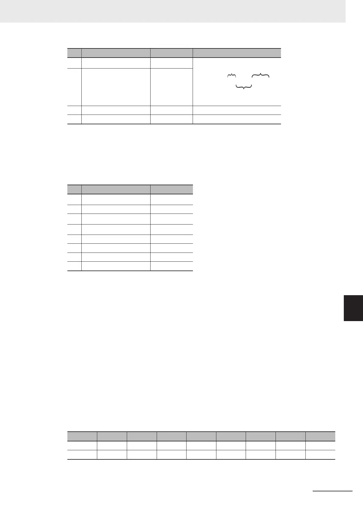
No. Field name Example (hex) Remarks
8
Changed data (MSB)
*3
17
Input terminal
D7, D6
Input terminal
D5 to D1
← 17 hex = 0000 0001 0111
Reserved
9
Changed data (LSB)
*3
00
10 CRC-16 (MSB) EB
11 CRC-16 (LSB) A2
*1. During a broadcast, no response will be sent back.
*2. Note that the coil start address is 0002 hex, which is 1 less than the coil number 0003 hex: Coil start
address = Coil number - 1.
*3. Since written data occupies both MSB and LSB as a set, make the data have an even number of bytes
by adding one byte of padding data, even if you actually need to change an odd number of bytes.
Response
No. Field name Example (hex)
1
Slave address
*1
01
2 Function code 0F
3
Coil start address (MSB)
*2
00
4
Coil start address (LSB)
*2
02
5 Number of coils (MSB) 00
6 Number of coils (LSB) 0C
7 CRC-16 (MSB) F4
8 CRC-16 (LSB) 0E
*1. During a broadcast, no response will be sent back.
*2. Note that the coil start address is 0002 hex, which is 1 less than the coil number 0003 hex: Coil start
address = Coil number - 1.
You can enable terminal commands using communications by enabling “4. RS-485 communication”
in 1st RUN Command Selection (F02)/2nd RUN Command Selection (E102). If enabling terminal
commands using RS-485 communications, refer to 7-2-1 Multifunction Input Selection on page
7-26 for the enable/disable relationship with the terminal block.
Multifunction input is monitored using a control circuit terminal for terminal block input (I/O) (monitor
mode 4_00), and communications control signal for communications input (I/O) (monitor mode
4_01).
If the Write to Multiple Coils function is not executed normally
, refer to 8-5-9 Exception Response
on page 8-20.
(Ex-
am-
ple)
When the status of coils from coil number 0001 to 000D hex is written, the order of data is as shown
below. Data 1 is the initial byte data to send.
bit 7 bit 6 bit 5 bit 4 bit 3 bit 2 bit 1 bit 0
Data 1 0008 hex 0007 hex 0006 hex 0005 hex 0004 hex 0003 hex 0002 hex 0001 hex
Data 2 - - - 000D hex 000C hex 000B hex 000A hex 0009 hex
8 Communications Functions
8-17
M1 Series Standard Type User's Manual (I669)
8-5 Explanation of Each Function Code
8
8-5-6 Write to Multiple Coils [0F hex]
 Loading...


