Disable Support Tool Link Function (y99 = 0)
This is activated by the command selected by RUN Command Selection (F02/E102) and Frequency
Reference selection (F01/C30).
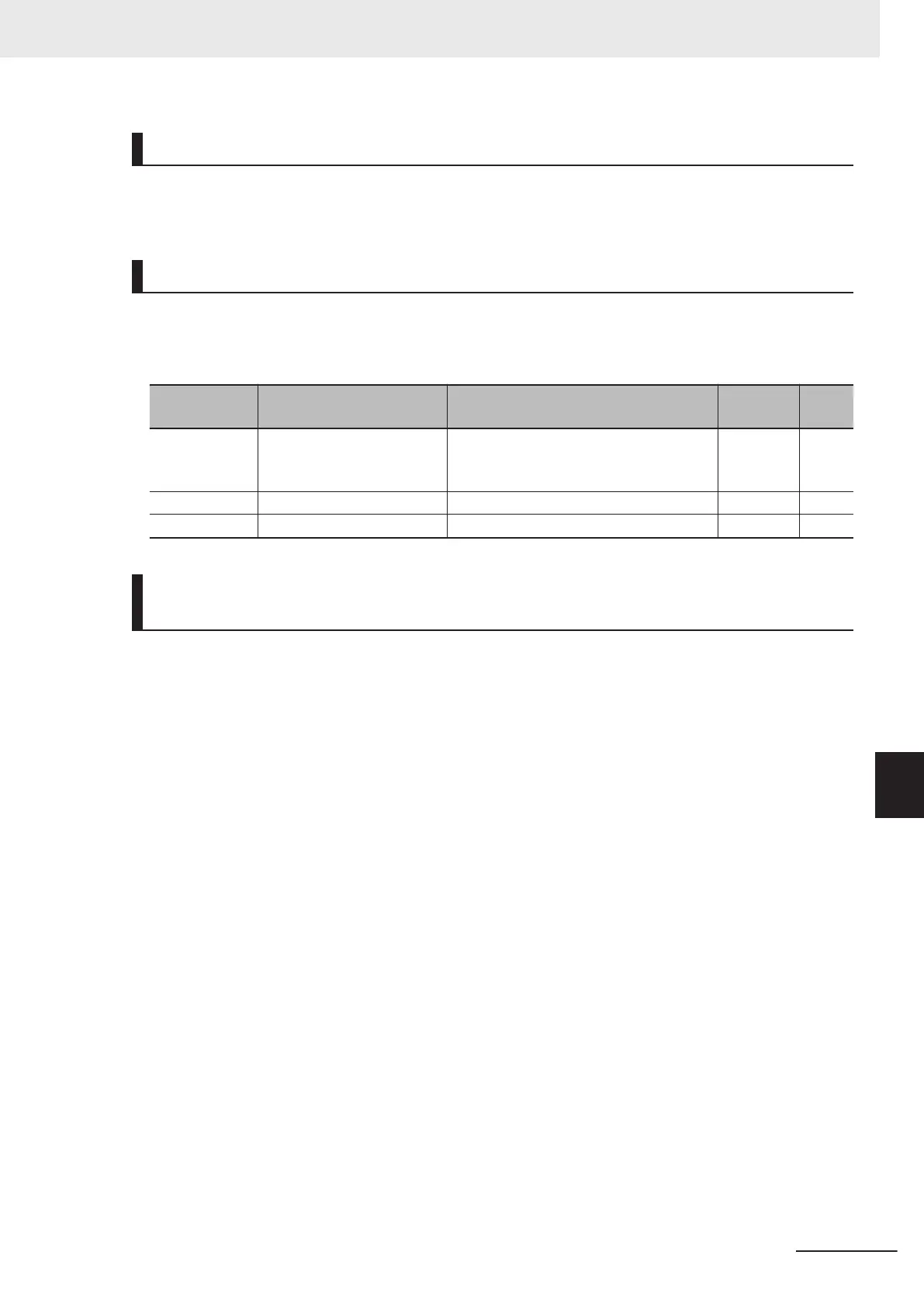
Enable Support Tool Link Function Command Value (y99 = 1, 3)
This is instructed by setting Frequency Reference (S01)/Torque Reference (S02)/Torque Bias Value
(S24) to the register No. of the applicable Modbus communication. (Refer to 8-9-2 Register List on
page 8-
36.)
Parameter No. Function name Data
Default
data
Unit
S01 Frequency Reference
-32,768 to 32,767
+20,000 or -20,000 = Maximum output
frequency
0 -
S02 Torque Reference -327.68 to 327.67 % 0 %
S24 Torque Bias Value -327 to 327 % 0 %
Enable Support Tool Link Function Universal I/O Terminals (y99 =
2, 3)
• Input terminals [DI1] to [DI7], output terminals [DO1] to [DO2] and [ROA, ROB], and analog output
terminal [AO] can be forcibly manipulated via communication by enabling universal I/O terminals.
• Normally, functions currently selected by Input T
erminal [DI1] to [DI7] Function Selection can be op-
erated not by signals that are input from input terminals [DI1] to [DI7] but by forcibly setting them via
communication.
• Output to output terminals [DO1], [DO2] and [ROA, ROB] and analog output terminal [AO] by setting
Communication Data Terminal [DO] (S07) and Communication Data Terminal [AO] (S12) and not the
output signal selected by Output Terminal [DO1] to [DO2] and [ROA, ROB] Function Selection or
Output Terminal [AO] Function Selection to the register No. of the applicable Modbus communica-
tion. (Refer to 8-9-2 Register List on page 8-36.)
8 Communications Functions
8-89
M1 Series Standard Type User's Manual (I669)
8-10 Command via Communications
8
8-10-3 Forced Commands via Communication

 Loading...


