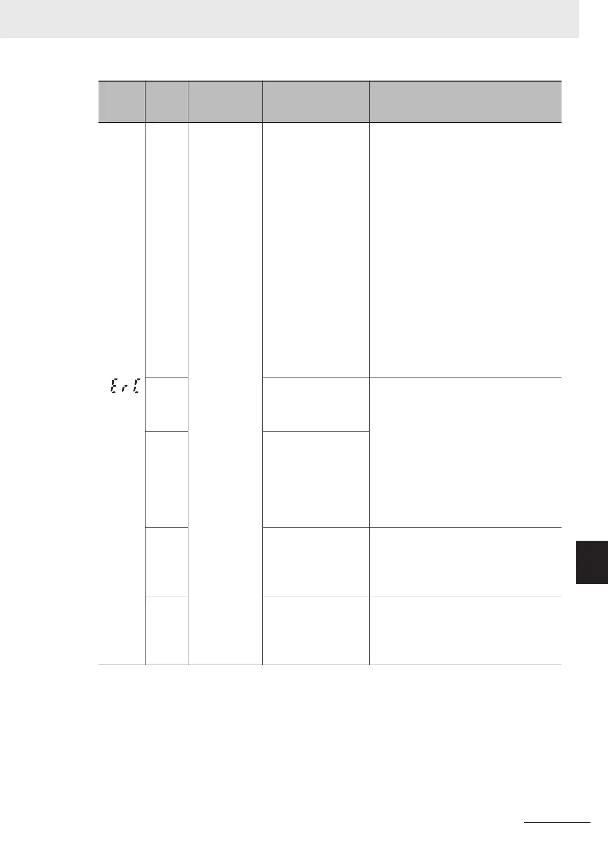
Alarm
code
Alarm
sub-
code
Name Description Check point and remedy reference
(ErC)
Magnetic pole
position detec-
tion error
(1) Inverter settings are
not appropriate
Check presence and model of the used mo-
tor
, and of the speed/magnetic pole position
sensor, and that 1st Drive Control Selection
(F42)/Input T
erminal [PIA][PIB] Pulse Input
Format Selection (d14) and Input Terminal
[PIA][PIB] Encoder Pulse Resolution (d15)
are coordinated.
→ Check the equipment configuration
(model and specifications of motor,
speed/magnetic pole position sensor),
and set F42/d14/d15 correctly.
Set the 1st PM Motor Starting Method (P30)
to 0 or 3, and check if the 1st PM Motor
Magnetic Pole position Offset (P95) is set to
“999: offset has not been adjusted.”
→
Set P95 correctly. (Auto-tuning also is
possible. Refer to Offline Auto-tuning of
Synchronous Motor (PM Motor) on
page 6-67.)
(2) Error with speed/
magnetic pole position
sensor connection
Check for errors with speed/magnetic pole
position sensor output wiring connection,
and the phase sequence of AB or UVW
phase.
(3) Motor rotation direc-
tion and sensor output
do not match
→ Correctly connect the feedback input
terminal block board with the speed/
magnetic pole position sensor.
Check for bad connections in the motor
wiring, and the phase sequence.
→ Ensure a correct connection with the in-
verter and motor.
(4) Error in terminal
block board connection
Check if the terminal block board connector
and inverter unit connector are correctly con-
nected.
→ Mount the terminal block board correct-
ly in the inverter unit.
(5) Strong noise re-
ceived from surrounds
Check measures against noise (grounding
conditions, signal wiring and communication
cable/main circuit wiring and installation
methods, etc.).
→
Implement measures against noise.
9 Troubleshooting
9-11
M1 Series Standard Type User's Manual (I669)
9-1 Alarm Display and Remedies
9
9-1-2 Alarm Code List
 Loading...