9-2
Troubleshooting
If you feel that the inverter operation is strange or that the inverter does not operate as intended, use
the following information as a reference, even if the inverter displays no alarm indication.
If the inverter trips with an alarm indication, refer to 9-1 Alarm Display and Remedies on page 9-2.
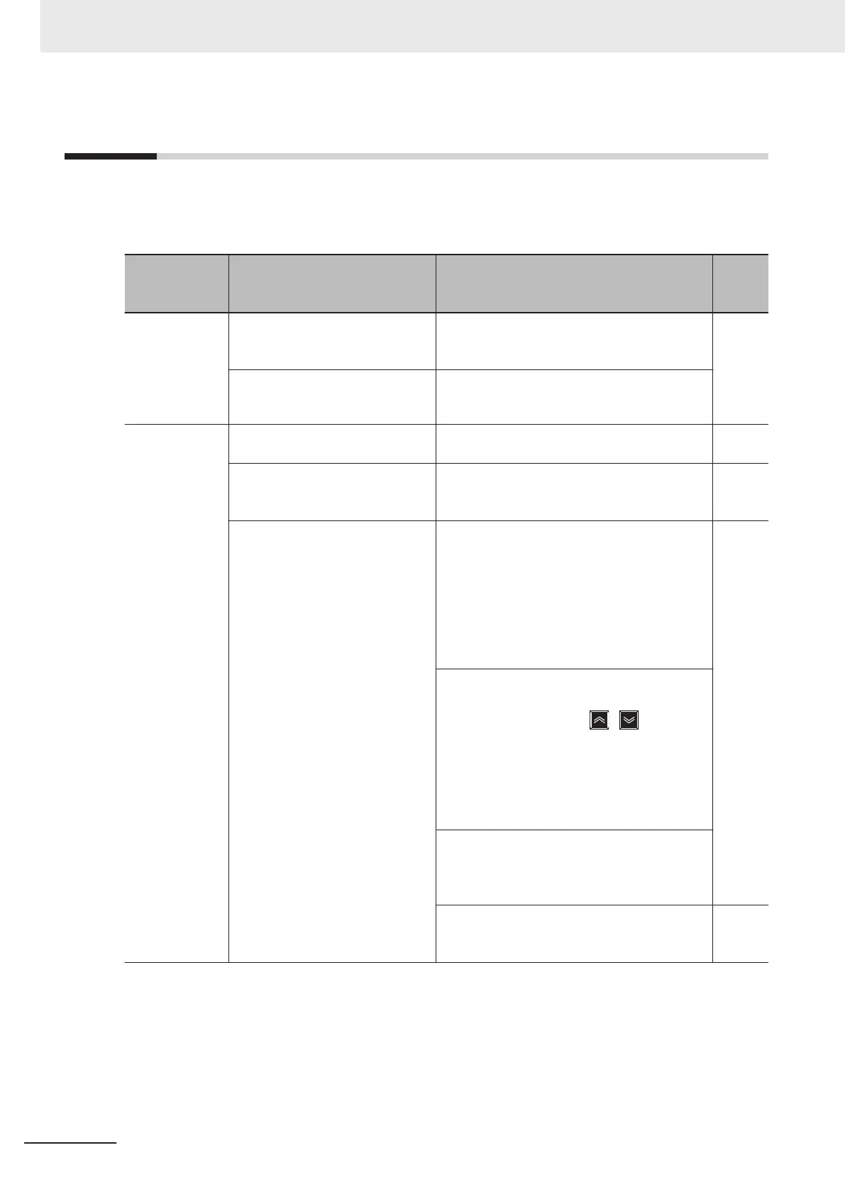
Symptom Possible cause Remedy
Refer-
ence
page
The power sup-
ply is not turned
on. (The POW
-
ER LED on the
inverter is not
lit.)
The short-circuit bar between the
terminal +1 and P/+2 is removed,
or no DC reactor is connected.
Install the short-circuit bar, or connect a DC re-
actor
. page
2-10
page
2-45
Input wiring is disconnected. Check the input wiring.
The RUN com-
mand is input,
but the motor
does not rotate.
1st RUN Command Selection
(F02) is incorrect.
Set 1st RUN Command Selection (F02) cor-
rectly.
page
5-25
1st Frequency Reference Selec-
tion (F01) is incorrect.
Set 1st Frequency Reference Selection (F01)
correctly according to the frequency reference
input method, and specify the frequency.
There frequency is set to 0 Hz. When the 1st Frequency Reference Selection
(F01) is set to “1, 2, 3, 5: Analog voltage in-
put,” input the analog voltage or current signal
corresponding to the frequency to the terminal
AI1 or AI2. For details on switching between
the analog voltage and current signals, refer to
5-5-1 Frequency Reference Selection on page
5-27.
page
5-
27
When the 1st Frequency Reference Selection
(F01) is set to “0: Digital Operator,” set the fre-
quency with the operator “
/ key.” The
set values are reflected in C99 (Digital Refer-
ence Frequency (multi-step speed reference
0)) / E109 (2nd Digital Reference Frequency
(2nd multi-step speed reference 0)) in accord-
ance with No. 1 control / No. 2 control.
Input the frequency according to the 1st Fre-
quency Reference Selection (F01). (The input
frequency will be displayed in the frequency
reference monitor (monitor mode: 3_02).)
For the multi-step speed operation, set the fre-
quency to the multi-step speed reference 0 to
15 (C99, E109, C05 to C19).
page
5-57
9 Troubleshooting
9-28
M1 Series Standard Type User's Manual (I669)

 Loading...