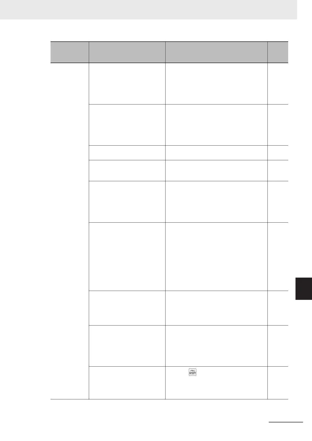
Symptom Possible cause Remedy
Refer-
ence
page
The RUN com-
mand is input,
but the motor
does not rotate.
No multifunction input terminal is
allocated for the RUN command.
To input the RUN command via a multifunction
input terminal, set the used terminal to “98:
FW (forward rotation)” or “99: RV (reverse ro-
tation).” To input the RUN command via the 3-
wire input function, set them to “98: FW
,” “6:
STP” and “97: F/R.”
page
5-55
page
5-56
Multi-step speed settings “0: CF1”
to “03: CF4” are set to the multi-
function input terminal, and these
are ON.
Disable the multi-step speed setting. (When
this setting is enabled, multi-step speed opera-
tion is performed, so the motor does not rotate
if the frequency values in the Multi-step Fre-
quency Reference 1 to 15 (C05 to C19) are 0
(default).)
page
5-57
Both the forward and reverse in-
put terminals are ON.
To input the RUN command via the forward/
reverse input terminal, turn ON either of them.
page
5-55
The Reverse Rotation Prevention
Function (H08) is set to limit the
forward or reverse rotation.
Set Reverse Rotation Prevention Function
(H08) correctly.
page
7-
117
The input terminal wiring or short-
circuit bar connection for the RUN
command is incorrect.
Wire correctly
. (The multi-function input termi-
nal status can be checked in the Input Termi-
nal Monitor (W40)/Output Signal Monitor
(W41).)
page
2-10
page
2-12
page
2-
51
The analog input or variable resis-
tor wiring for the frequency refer-
ence is incorrect.
Wire correctly.
• For the analog voltage or variable resistor
input, measure the voltage between the ter-
minals AI1 to AIC or AI2 to AIC with a tester
etc. to check that the voltage is correct.
• For the analog current input, with the wires
disconnected, measure the current flowing
between the power supply and AII terminals
with a tester etc. to check that the current is
correct.
page
2-10
page
7-35
Although the inverter is operated
via the digital operator, the multi-
function input terminal is set to
“162: F-TM (Forced terminal
block)” and that terminal is ON.
Turn OFF the terminal to which the function is
allocated.
page
7-75
Although the inverter is operated
via the control circuit terminal
block, the multifunction input ter-
minal is set to “35 OPE (Forced
operator function)” and that termi-
nal is ON.
T
urn OFF the terminal to which the function is
allocated.
page
7-75
An inverter trip occurred. (The
ERR LED lights and the alarm
code is displayed)
Press the
key to reset the trip and, after
determining the cause and taking counter-
measures based on the alarm code, restart
the inverter.
page
5-
49
page
9-
2
9 Troubleshooting
9-29
M1 Series Standard Type User's Manual (I669)
9-2 Troubleshooting
9
 Loading...