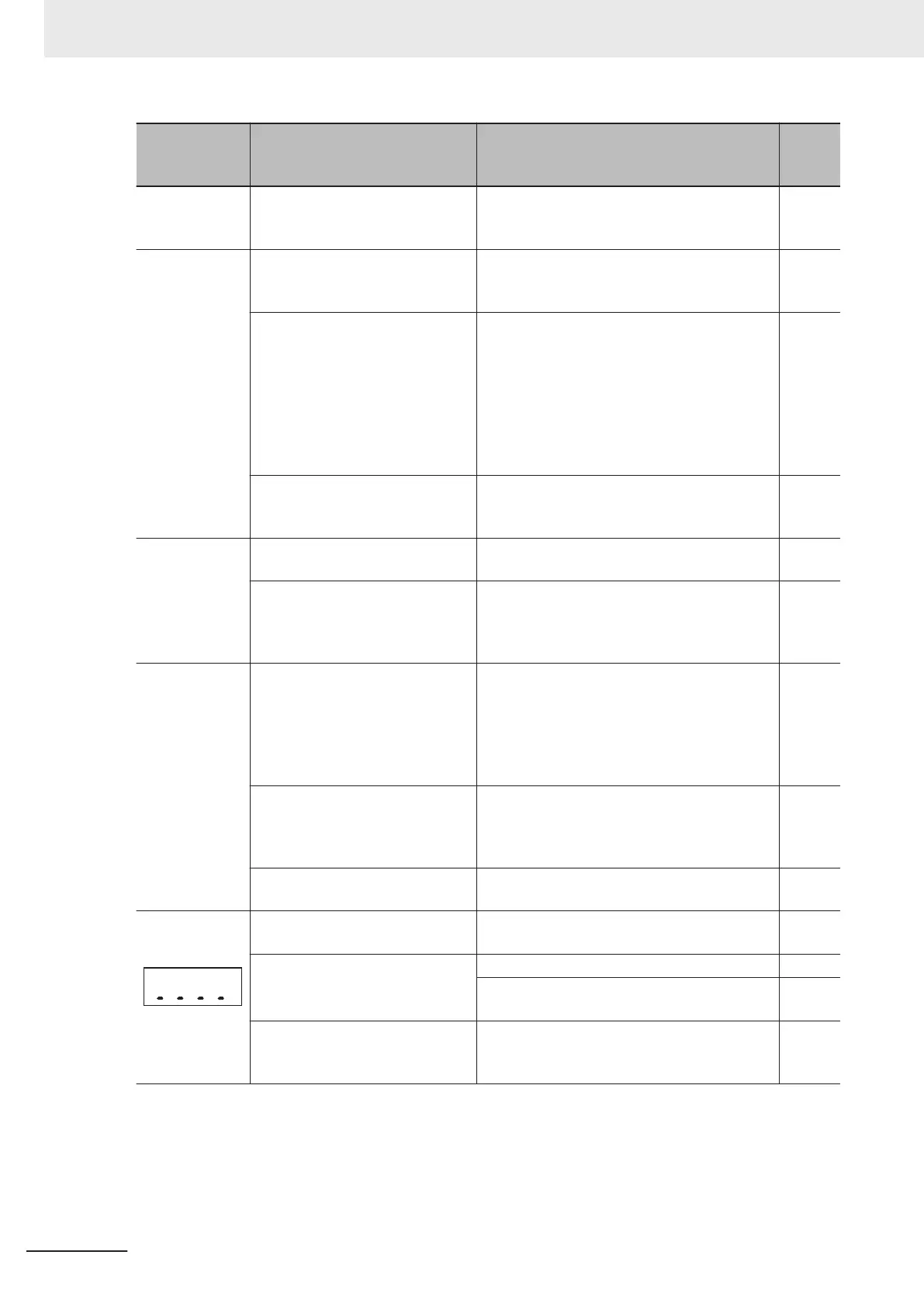
Symptom Possible cause Remedy
Refer-
ence
page
Brake transistor
error (dbA) oc-
curred.
The brake transistor is damaged. Replace the inverter.
-
Brake error
(Er6) occurred.
The output current does not reach
the set brake release current val-
ue.
Increase the Brake Control Brake-release Tim-
er (J70) or decrease the Brake Control Brake-
release Current (J68).
page
6-
72
The brake confirmation signal is
not input.
• Correct the wiring for the brake confirmation
signal (57: BRK). If not used, deallocate the
brake confirmation function from the multi-
function input setting.
• Review the operation sequence so that the
brake confirmation signal (57: BRK) is input
after the brake is released.
• Replace the brake if it is faulty.
page
6-72
Brake confirmation signal is not in-
put within the time set in Brake Er-
ror Detection Time (H180).
Adjust the Brake Error Detection Time (H180).
page
6-72
The brake con-
trol function
causes the load
to fall.
The set brake release current is
insufficient.
Increase the Brake Control Brake-release Cur-
rent (J68) value.
page
6-72
The frequency setting for releas-
ing/forcing the brake is too low.
Increase the Brake Control Brake-release Fre-
quency (J69), Brake Force Frequency (J71),
or Brake Control Brake-applied Frequency
(J71) setting values.
page
6-
72
The PM motor
rotates during
startup.
The magnetic pole position of the
motor during startup is incorrect.
Set the 1st PM Motor Starting Method (P30) to
“1: IPM (Embedded magnet motor method 1),”
and reduce initial rotation at startup. If 0 or 3
are used in P30, reduce 1st PM Motor Refer-
ence Current at Starting (P74) to make re-
verse rotation more difficult.
page
6-22
The PM motor stalls. Increase the 1st PM Motor Reference Current
at Starting (P74) value. Or perform adjust-
ments according to 6-4-4 Adjustment of PM
Motor Mode Settings on page
6-22
.
page
6-22
The load is too heavy. Reduce the load. Or, increase the accelera-
tion/deceleration time.
-
Underbar dis-
play
(1) The Main Circuit DC Voltage is
dropped
• Connect a power supply with voltage speci-
fications that match the input voltage.
-
(2) Only control power supply aux-
iliary input on, without main power
supply.
• Turn the power supply ON.
-
• Install a shorting bar or DC reactor between
terminal P1 and P(+), or tighten screws.
page
2-11
(3) Main power supply input termi-
nal wiring disconnected
• Repair or replace the main power supply in-
put wiring or input equipment (molded case
circuit breaker, magnetic contactor, etc.)
page
2-15
9 Troubleshooting
9-36
M1 Series Standard Type User's Manual (I669)
 Loading...


