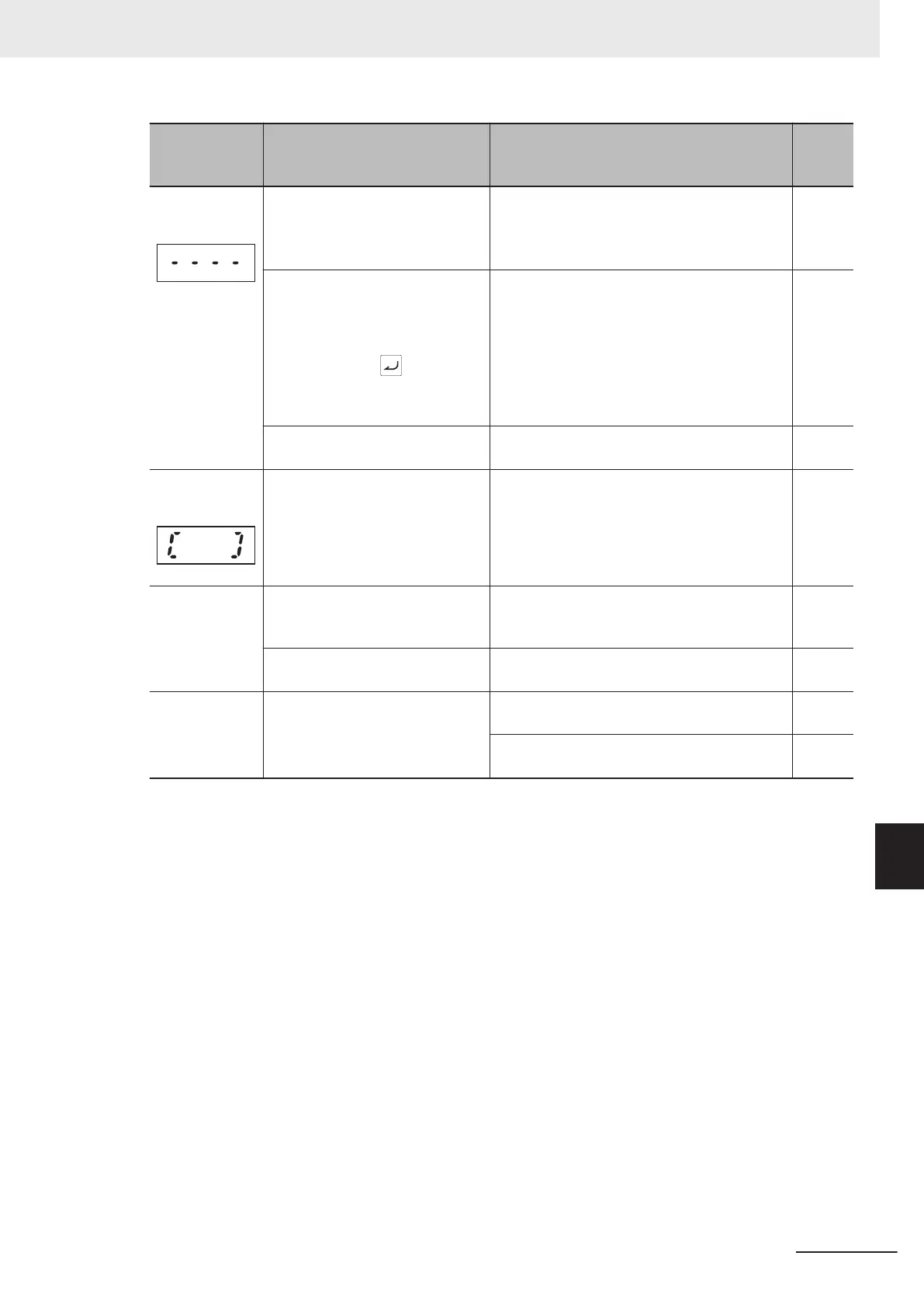
Symptom Possible cause Remedy
Refer-
ence
page
Center bar dis-
play
(1) With PID control not operating
(J01 = 0), Operator Display Se-
lection during Run (E43) is set to
10 or 12
• Set E43 to other than 10 or 12.
page
7-76
While PID control is operating
(J01 = 1, 2, 3), and “PID process
command” or “PID feedback val-
ue” set to display on the LED
monitor using the key, PID
control has been set to disable
(J01 = 0).
• T
urn J01 to 1, 2, or 3.
page
7-123
(2) Operator connection error
• Replace the remote operation extension ca-
ble.
-
Parentheses
display
(1) Displayed data is an overflow
• Review E50 data.
page
7-76
The parameter
settings cannot
be changed
(changed from
link function)
(1) Attempted to change a param-
eter that cannot be changed dur-
ing operation
• Stop operation and then change the param-
eter
.
-
(2) Parameter F02 data cannot be
changed
• Turn both terminal signals “FW” and “RV”
OFF
.
page
5-55
Underbar and
En display
(1) SF1 and SF2 terminals are
OFF
• Turn SF1 and SF2 ON.
page
7-69
• When FW/RV signals are ON, turn the
FW/RV signals OFF
.
page
5-55
9 Troubleshooting
9-37
M1 Series Standard Type User's Manual (I669)
9-2 Troubleshooting
9

 Loading...


