16
Chapter2
OS32C
User’s Manual
Operating States & Output Modes
During normal operation:
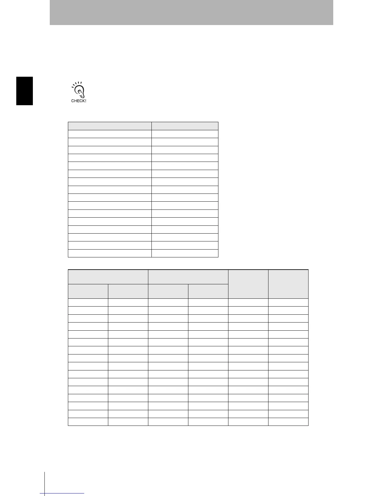
The seven-segment display indicates the current zone set and response time of the OSSDs. For
example, code 24 indicates zone set 2 with a response time of 160ms.
When the display is inverted, a decimal will be shown in the corner.
The response times longer than 400ms are represented by zero.
Left Digit
Right Digit
* The OFF to ON response time is the sum of the corresponding ON to OFF response time and the Restart Delay parameter.
See p.49 for configuring the Restart Delay parameter.
Table 2-5 Status/Diagnostic Display Indication
Monitoring Zone of OS32C Digital Indication
Zone Set 1 1
Zone Set 2 2
Zone Set 3 3
Zone Set 4 4
Zone Set 5 5
Zone Set 6 6
Zone Set 7 7
Zone Set 8 8
Zone Set 9 9
Zone Set 10 A
Zone Set 11 b
Zone Set 12 C
Zone Set 13 d
Zone Set 14 E
Zone Set 15 F
Zone Set 16 or higher U
Response Time (ms)
(OSSDs output)
Response Time (ms)
(Auxiliary and Warning Output)
Digital Indication Scan Count
ON to OFF
OFF to ON
(Configurable)*
ON to OFF
OFF to ON
(Configurable)*
80 ms 180 ms to 60.08s 120 ms 220 ms to 60.12s 2 2
120 ms 220 ms to 60.12s 160 ms 260 ms to 60.16s 3 3
160 ms 260 ms to 60.16s 200 ms 300 ms to 60.2s 4 4
200 ms 300 ms to 60.2s 240 ms 340 ms to 60.24s 5 5
240 ms 340 ms to 60.24s 280 ms 380 ms to 60.28s 6 6
280 ms 380 ms to 60.28s 320 ms 420 ms to 60.32s 7 7
320 ms 420 ms to 60.32s 360 ms 460 ms to 60.36s 8 8
360 ms 460 ms to 60.36s 400 ms 500 ms to 60.4s 9 9
400 ms 500 ms to 60.4s 440 ms 540 ms to 60.44s 0 10
440 ms 540 ms to 60.44s 480 ms 580 ms to 60.48s 0 11
480 ms 580 ms to 60.48s 520 ms 620 ms to 60.52s 0 12
520 ms 620 ms to 60.52s 560 ms 660 ms to 60.56s 0 13
560 ms 660 ms to 60.56s 600 ms 700 ms to 60.6s 0 14
600 ms 700 ms to 60.6s 640 ms 740 ms to 60.64s 0 15
640 ms 740 ms to 60.64s 680 ms 780 ms to 60.68s 0 16
680 ms 780 ms to 60.68s 720 ms 820 ms to 60.72s 0 17
 Loading...