208
Motion Perfect Tools Section 7-5
operation again or to just by removing the line manually. All breakpoints can
be removed from a program by selecting Clear All Breakpoints from the
Debug Menu.
7-5-3 Axis Parameters
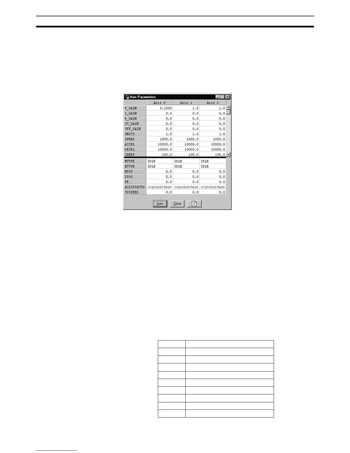
The Axis Parameters Window allows the user to set and read the axis param-
eter settings. This window works like a Windows-based spread sheet. The
Axis Parameter Window is shown below.
The Axis Parameters Window is made up of a table of cells separated into two
banks, bank 1 at the top and bank 2 at the bottom.
• Bank 1 contains the values of parameters that can be changed by the
user. The values can be changed by clicking on it and entering the new
value.
• Bank 2 is read-only and contains the values which are set by the system
software of the MC Unit as it processes the BASIC commands and moni-
tors the status. These values are updated continuously at a specified rate.
The following operations are possible on the Axis Parameters Window.
• The user is able to change the size of the window. The black dividing bar
can be repositioned to change the space occupied by the two banks.
• When the user changes the UNITS parameter for an axis, all the parame-
ters given in user units for that axis will be adjusted by the new factor.
These new values will loaded automatically in the screen.
• The AXISSTATUS parameter field displays the axis status bits. The char-
acters indicating each bit will turn red and capital if the bit is ON and
green if the bit is OFF. The ‘ocyxehdrfmaw’ characters correspond to
w Following Error Warning
a Servo Driver Communication Error
m Servo Driver Alarm
fForward Limit
r Reverse Limit
dDatuming
h Feed Hold Input
e Following Error Limit
x Forward Software Limit
y Reverse Software Limit