24
Components and Unit Settings Section 2-1
2-1 Components and Unit Settings
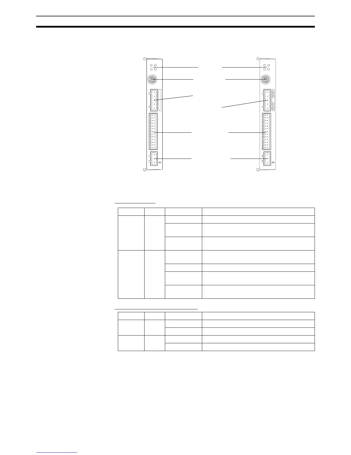
The following diagram shows the main components of the MC Unit.
Indicators
The following table describes the indicators on the front of the MC Unit.
■ Motion Control
■ RS-422A/485 (MCW151-E only)
PO RT 0 , 1
RUN ST S
I/O
+ 24V
0V
25
1
26
2
SD RD
MCW151
PORT2
PO RT 0 , 1
MCW1 51-DRT
RUN
MS
STS
NS
I/O
+ 24V
0V
25
1
26
2
Indicators
I/O Connector
RS-232C Ports
Connector
RS-422A/485 Port
Connector
Power Connector
DeviceNet
Connector
Indicator Color Status Meaning
RUN Green ON The MC Unit is operating normally.
OFF The MC Unit did not start properly or is not pow-
ered on.
Flashing with
STS
An error occurred in the communication with the
Servo Driver.
STS Red ON The axis has been disabled. The Servo Enable
is not ON.
OFF The axis is enabled.
Flashing alone A motion error has occurred. The Servo Driver
has been disabled.
Flashing with
RUN
An error occurred in the communication with the
Servo Driver.
Indicator Color Status Meaning
SD Green ON Transmitting data.
OFF No communication.
RD Green ON Receiving data.
OFF No communication.