30
Wiring Section 2-3
2-3 Wiring
2-3-1 Control Connections
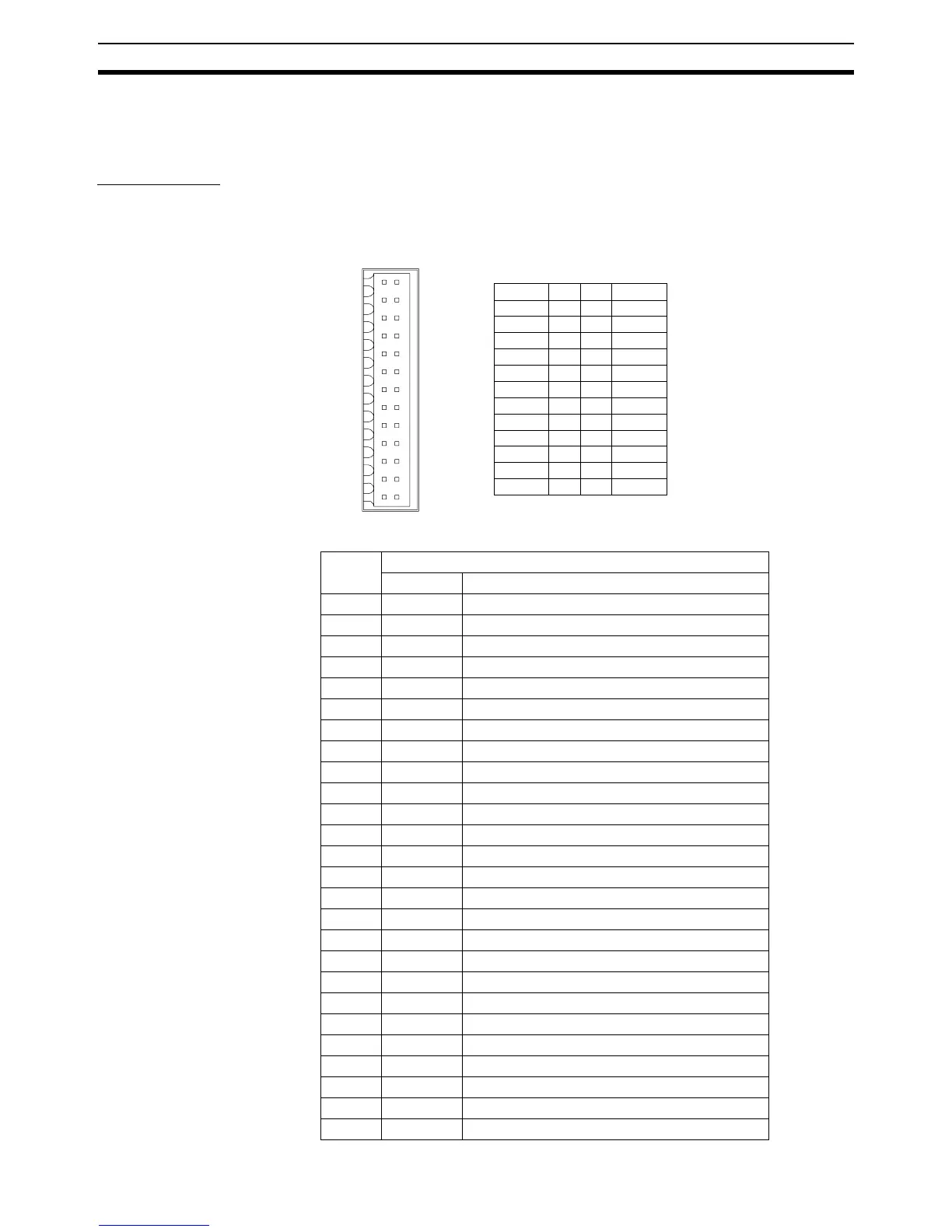
I/O Connector
The I/O Connector is used for wiring to the digital I/O and the connection for
the encoder input or encoder output. Refer to 2-3-4 I/O Specifications for elec-
trical specifications.
Connector pin
arrangement
I/O Connector Pin
Functions
A+ 1 2 A-
B+ 3 4 B-
Z+ 5 6 Z-
0V_ENC 7 8 5V_ENC
I0 / R0 9 10 FG
I2 11 12 I1 / R1
I4 13 14 I3
I6 15 16 I5
0V_IN 17 18 I7
O8 19 20 O9
O102122O11
O122324O13
0V_OP 25 26 24V_OP
I/O
25
1
26
2
Pin Signal
Name Function
1 A+ Encoder phase A+ (Input / Output)
2 A- Encoder phase A- (Input / Output)
3 B+ Encoder phase B+ (Input / Output)
4 B- Encoder phase B- (Input / Output)
5 Z+ Encoder phase Z+ (Input / Output)
6 Z- Encoder phase Z- (Input / Output)
7 0V_ENC Encoder 0V common
8 5V_ENC Encoder 5V power supply output
9 I0 / R0 (Registration) Input 0
10 FG Frame Ground
11 I2 Input 2
12 I1 / R1 (Registration) Input 1
13 I4 Input 4
14 I3 Input 3
15 I6 Input 6
16 I5 Input 5
17 0V_IN Inputs 0V common
18 I7 Input 7
19 O8 Output 8
20 O9 Output 9
21 O10 Output 10
22 O11 Output 11
23 O12 Output 12
24 O13 Output 13
25 0V_OP Outputs 0V common
26 24V_OP Outputs 24V power supply input