50
System Functions Section 3-3
■ Speed Limit Settings
During torque control, it is advisable to limit the Servomotor speed by using
the speed reference. The required Servo Driver setting is Pn002.1=1 and
please refer to the Speed Control section above for details on the speed refer-
ence in open loop.
3-3-2 Digital I/O
The MC Unit has two different types of digital I/O. These are the digital I/O on
the MC Unit and the mapping of the Servo Driver digital I/O. The inputs and
outputs are accessible by using the IN and OP commands in BASIC.
Input Mapping
■ MC Unit Digital Inputs
The MC Unit inputs are freely allocable to different functions. Some of the
functions are origin search, limit switches, jog inputs and so on. The MC Unit
uses axis parameters to allocate a certain function to an input. The following
table introduces the related axis parameters.
■ Servo Driver Digital Inputs
The digital inputs of the Servo Driver (CN1-40 to CN1-46) can be directly
accessed from the MC Unit. The mapping of the inputs is specified in the fol-
lowing table.
■ Servo Driver Output Signals
The relevant Servo Driver output signals can be monitored in the MC Unit.
The mapping of the output signals is specified in the following table.
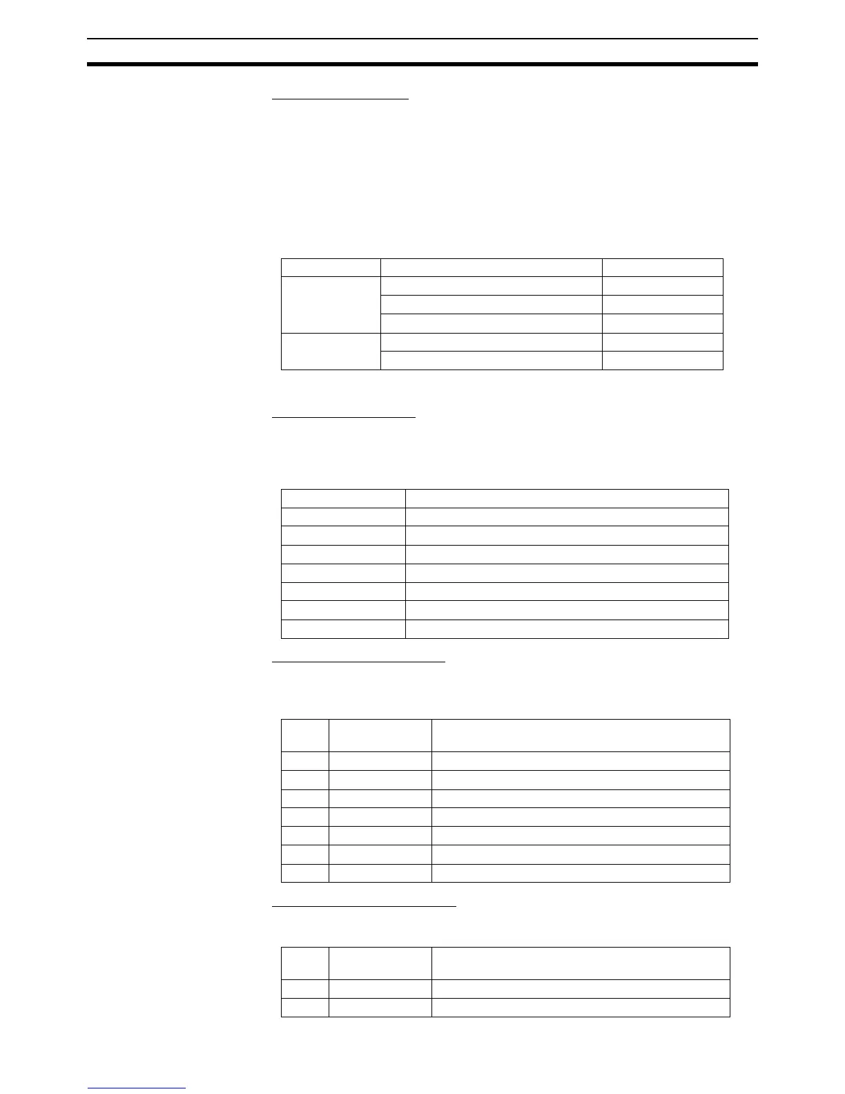
Type Description Range (amount)
Input mapping MC Unit Digital Inputs 0 - 7 (8)
Servo Driver Digital Inputs 16 - 22 (7)
Servo Driver Output Signals 24 - 31 (8)
Output mapping MC Unit Digital Outputs 8 - 13 (6)
Servo Driver Control Signals 16 - 17 (2)
Parameters Description
DATUM_IN Selection origin switch input
FAST_JOG Selection of fast jog input
FHOLD_IN Selection of feedhold input
FWD_IN Selection of forward limit input
FWD_JOG Selection of forward jog input
REV_IN Selection of reverse limit input
REV_JOG Selection of reverse jog input
Input
nr.
Servo Driver
Input
Description (according to required Servo Driver
settings)
16 CN1-40 General purpose 1
17 CN1-41 General purpose 2
18 CN1-42 Forward drive prohibit (POT) / General purpose 3
19 CN1-43 Reverse drive prohibit (NOT) / General purpose 4
20 CN1-44 General purpose 5
21 CN1-45 General purpose 6
22 CN1-46 Registration input / General purpose 7
Input
nr.
Servo Driver
Signal
Description
24 ALM Alarm output
25 WARN Overload or regenerative overload warning output