46
System Set-up Section 3-2
• The Display will not be lit for some seconds during start-up (either by
power-up or software reset).
• The Display will not be lit for some time when the following commands are
executed in the MC Unit:
• Reading and writing Servo Driver parameters.
• Clearing the alarm status of the Servo Driver.
3-2 System Set-up
Servo Driver Settings
The Servo Driver is required to have the following settings. Refer to the
OMNUC W-series User’s manual (I531) for details.
Servo Cycle Period
Setting
The MC Unit SERVO_PERIOD system parameter can be used to set the MC
Unit Servo Cycle and the Servo Driver communication access time. The fol-
lowing values are valid:
SERVO_PERIOD = 500 s (default)
SERVO_PERIOD = 1000 s
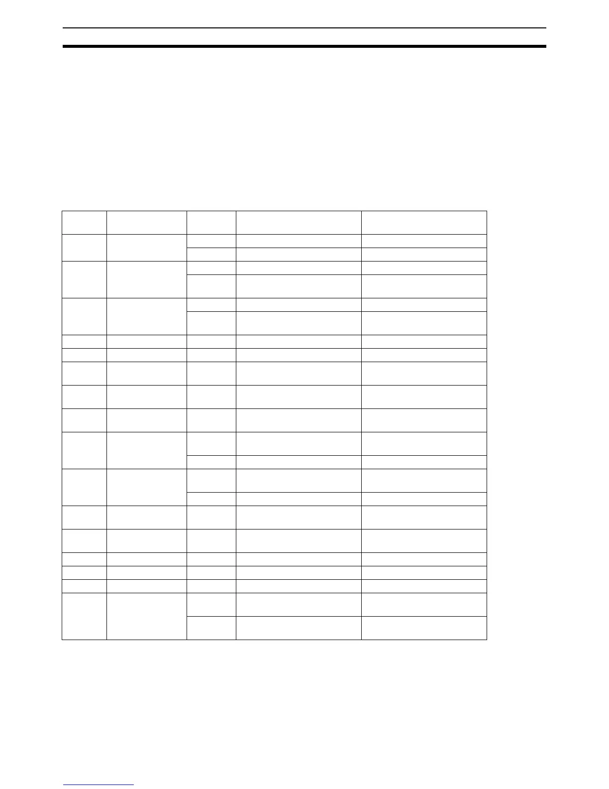
Param-
eter No.
Parameter Name Required
Setting
Explanation Remark
Pn000.1 Control Mode
Selection
0 Speed Control
9 Torque / Speed Control
Pn002.0 Torque command
input (during
speed control)
0 Not used
1 Use TREF as analog torque
limit input
Pn002.1 Speed command
input (during
torque control)
0 Not used
1 Use (S)REF as analog speed
limit input
Pn003.0 Monitor 1 2 Torque Reference Monitor
Pn003.1 Monitor 2 0 Motor Speed Monitor
Pn50A.0 Input Signal Allo-
cation Mode
1 User-defined
Pn50A.1 RUN Signal Input
Allocation
8 Always disabled Switch is controlled by the MC
Unit.
Pn50A.2 MING Signal Input
Allocation
8 Always disabled Switch is controlled by the MC
Unit.
Pn50A.3 POT Signal Input
Allocation
2 Assigned to CN1, pin 42 (valid
for low input)
8 Always disabled
Pn50B.0 NOT Signal Input
Allocation
3 Assigned to CN1, pin 43 (valid
for low input)
8 Always disabled
Pn50B.1 RESET Signal
Input Allocation
8 Always disabled Switch is controlled by the MC
Unit.
Pn50C.3 TVSEL Signal
Input Allocation
8 Always disabled Switch is controlled by the MC
Unit.
Pn511.0 - 8 Always disabled
Pn511.1 - 8 Always disabled
Pn511.2 - 8 Always disabled
Pn511.3 /EXT3 (Print Reg-
istration) Signal
Input Allocation
6 Assigned to CN1, pin 46 (valid
for low input)
Print registration on rising
edge.
F Assigned to CN1, pin 46 (valid
for high input)
Print registration on falling
edge.