25
Components and Unit Settings Section 2-1
■ DeviceNet (MCW151-DRT-E only)
Switch Settings
The MCW151 Units are equipped with the following DIP-switches.
■ DeviceNet Switch Settings (MCW151-DRT-E only)
The external switch settings will set the Slaves’ node address setting and
baud rate setting.
Node address
The node address of the slave is set with pins 1 through 6 of the DIP switch.
Any node address within the setting range can be used as long as it is not
already set on another node.
Indi
ca-
tor
Color Status Definition Meaning
MS Green ON Device
Operational
Normal operating status.
Flashing Device in
Standby
Reading switch settings.
Red ON Unrecover-
able Fault
Unit hardware error: Watchdog timer error.
Flashing Minor Fault Switch settings incorrect.
--- OFF No Unit
Power
Unit power is not supplied, waiting for initial
processing to start, or the Unit is being reset.
NS Green ON Link OK.
Online, Con-
nected.
Network is operating normally (communica-
tions established).
Flashing Online, Not
connected
Network is operating normally, but communi-
cations have not yet been established.
Red ON Critical Link
Failure
A fatal communications error has occurred.
Network communications are not possible.
Flashing Connection
Timeout
Communications timeout.
--- OFF No Fieldbus
Power / Not
Online
Checking for node address duplication on the
Master, switch settings are incorrect, or field-
bus power is not supplied.
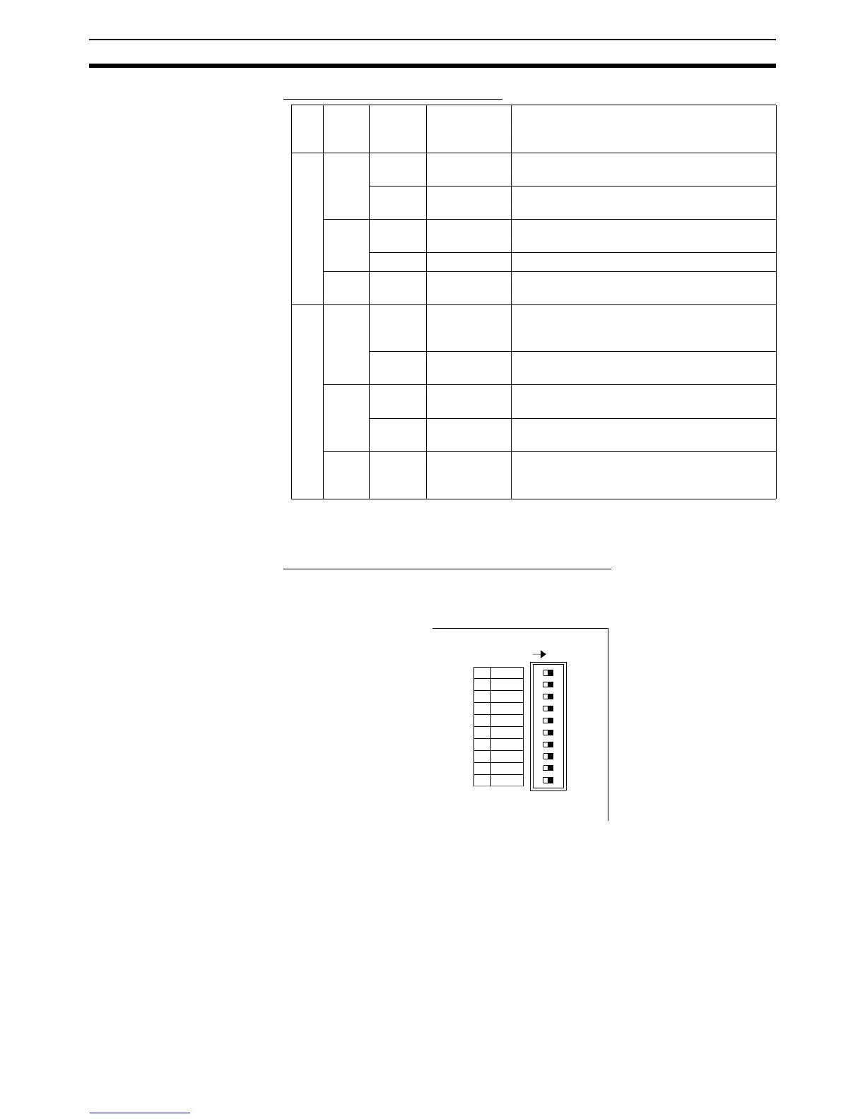
1 2
3
4
56
7
8910
ON
1 NA0
NA1
2
NA2
3
NA3
4
NA4
5
NA5
6
MD0
7
NC
8
DR0
9
DR1
10
ON