26
Components and Unit Settings Section 2-1
0: OFF, 1: ON
Baud rate
Pins 9 and 10 are used to set the baud rate as shown in the following table.
Note 1. Always turn OFF the MC Unit’s power supply (including the communica-
tions power supply) before changing the baud rate setting.
2. Set the same baud rate on all of the nodes (master and slaves) in the Net-
work.
Other settings
Pin 7 is used to select the I/O Slave Messaging mode. This determines the
allocation of the I/O Slave Messaging mode area.
Pin 8 is not used.
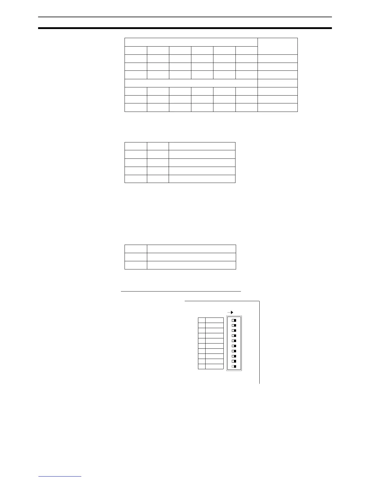
■ General Switch Settings (MCW151-E only)
For the MCW151-E the external DIP switch can be used for general purpose.
The value of the switch can be accessed using the SWITCH_STATUS param-
eter.
DIP switch setting Node address
Pin 6 Pin 5 Pin 4 Pin 3 Pin 2 Pin 1
0000000 (default)
0000011
0000102
... ...
11110161
11111062
11111163
Pin 10 Pin 9 Baud rate
OFF OFF 125 kbps (default)
OFF ON 250 kbps
ON OFF 500 kbps
ON ON Not allowed
Pin 7 I/O Slave Messaging Mode
OFF Mode I (default)
ON Mode II
1
1SW1
SW22
SW33
SW44
SW5
5
SW66
SW77
SW88
SW9
9
SW1010
2
3
4
56
7
8910
ON
ON