27
Components and Unit Settings Section 2-1
0: OFF, 1: ON
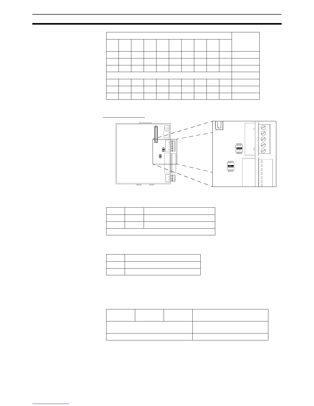
■ Internal Switches
Switch SW2 (MCW151-E only)
Pin 1 and 2 select the serial communication for port 2.
Pin 3 selects the termination resistor between receive pins (RD+ / RD -) for
port 2.
Pin 4 is not used.
Switch SW3
Pin 1 through 3 enable the termination resistor for the encoder channel A, B
and Z.
Pin 4 is not used.
DIP switch setting Parameter
value
Pin
10
Pin
9
Pin
8
Pin
7
Pin
6
Pin
5
Pin
4
Pin
3
Pin
2
Pin
1
00000000000 (default)
00000000011
00000000102
... ...
11111111011021
11111111101022
11111111111023
123
ON
4
123
ON
4
SW2
SW3
123
ON
4
12
3
ON
4
SW2
SW3
Pin 2 Pin 1 Selection
OFF OFF RS-422A (default)
ON ON RS-485
Other not allowed
Pin 3 Selection
OFF Termination disabled (default)
ON Termination enabled
Pin 3
(channel Z)
Pin 2
(channel B)
Pin 1
(channel A)
Selection
OFF Termination disabled for channel
(default)
ON Termination enabled