16
Control System Configuration Section 1-4
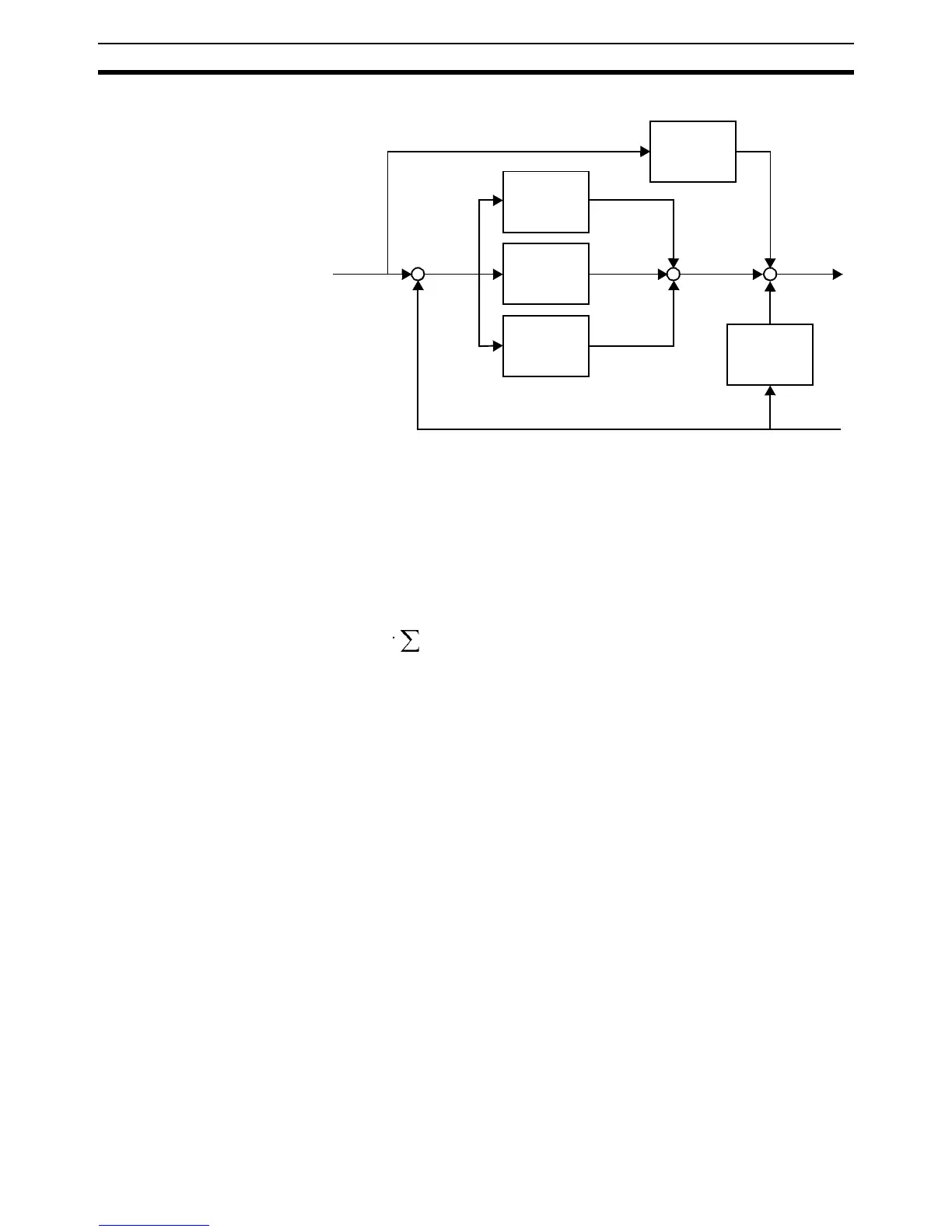
The Motion Control algorithm of the MC Unit is shown in the diagram below.
Proportional Gain The proportional gain creates an output that is proportional to the
following error .
All practical systems use proportional gain. For many just using this gain
parameter alone is sufficient. The proportional gain axis parameter is called
P_GAIN.
Integral Gain The integral gain creates an output that is proportional to the sum of
the following errors that have occurred during the system operation.
Integral gain can cause overshoot and so is usually used only on systems
working at constant speed or with slow accelerations. The integral gain axis
parameter is called I_GAIN.
Derivative Gain The derivative gain produces an output that is proportional to the
change in the following error and speeds up the response to changes in
error while maintaining the same relative stability.
Derivative gain may create a smoother response. High values may lead to
oscillation. The derivative gain axis parameter is called D_GAIN.
Output Speed Gain The output speed gain produces an output that is proportional to
the change in the measured position and increases system damping.
The output speed gain can be useful for smoothing motions but will generate
high following errors. The output speed gain axis parameter is called
OV_GAIN.
Speed Feedforward Gain The speed feedforward gain produces an output that is propor-
tional to the change in demand position and minimizes the following error
at high speed.
The parameter can be set to minimise the following error at a constant
machine speed after other gains have been set. The speed feed forward gain
axis parameter is called VFF_GAIN.
Demand
position
K
p
Following
error
K
i
Σ
K
d
∆
K
vff
∆
K
ov
∆
Measured
position
+
-
++
Output
signal
K
p
O
p
E
O
p
K
p
E⋅=
K
i
O
i
E
O
i
K
i
E
å
⋅=
K
d
O
d
E
O
d
K
d
E∆⋅=
K
ov
O
ov
P
m
O
ov
K
ov
P
m
∆⋅=
K
vff
O
vff
P
d
O
vff
K
vff
P
d
∆⋅=