18
Control System Configuration Section 1-4
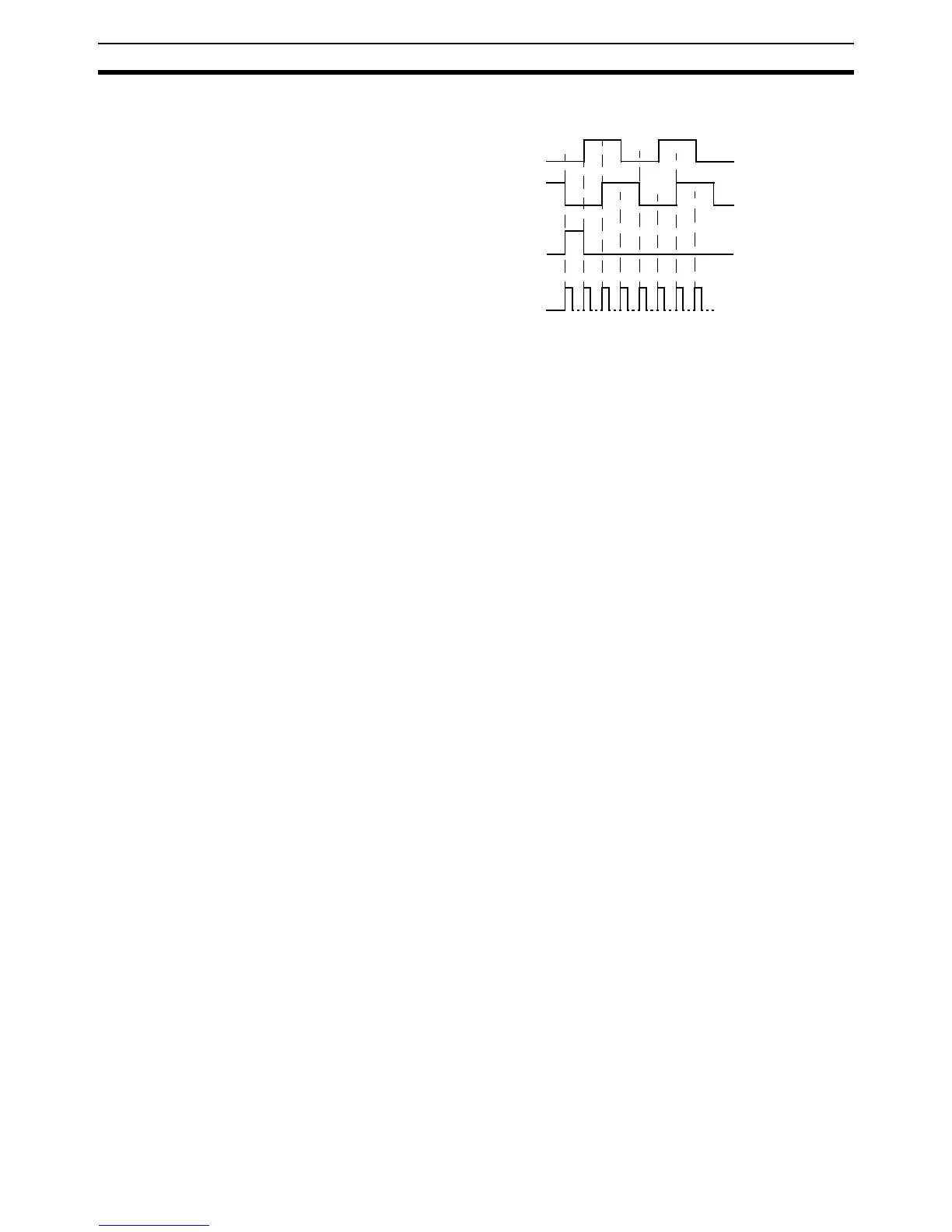
Encoder output For encoder output, the pulse ratio is 64. For every 16 internal counts one
encoder edge for one of the two phases will be produced.
The Z-phase signal has the following specification:
• The Z-marker has a period of 4096 generated edges.
• The pulse has a width of a quarter pulse period length (when both phase
A and B are low).
• The Z-phase signal is active after power-on.
The generated frequency is limited to the maximum allowable frequency. If
the internal speed would result in a frequency above this maximum, an axis
status flag will be set. See 8-2-1 MC Unit Error Handling for details.
Phase A
Phase B
Internal Counts
016 6432 48 80 96
Phase Z