64
Serial Communications Section 4-1
Examples: Consider the following operations for a MC Unit connected to a PC using
port 2 (RS-422A). The Slave PC has node address 13.
■ Reading data from PC using HLM_READ
BASIC program:
‘ Set up Host Link Master for port 2
SETCOM(9600,7,2,2,2,6)
‘ Source address: CIO/IR 002
‘ Amount of data: 2 words
‘ Destination address: VR(0)
HLM_READ(2,13,PLC_IR,2,2,MC_VR,0)
Host Link Communication:
HLM -> HLS: @13RR0002000242*
HLS -> HLM: @13RR000101010241*
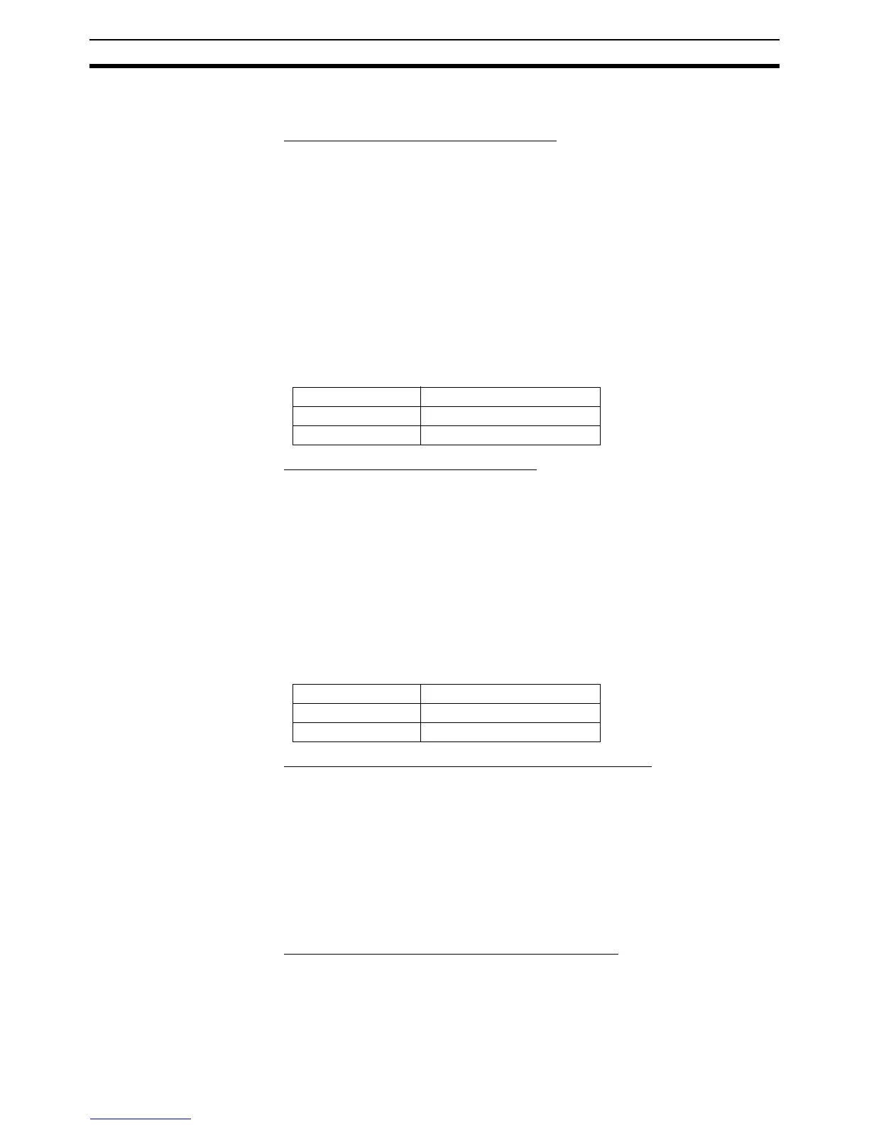
Result:
■ Writing data to PC using HLM_WRITE
BASIC program:
‘ Source address: Table(18)
‘ Amount of data: 2 words
‘ Destination address: LR 014
TABLE(18,$0701,$0702)
HLM_WRITE(2,13,PLC_LR,14,2,MC_TABLE,18)
Host Link Communication:
HLM -> HLS: @13WL0014070107025F*
HLS -> HLM: @13WL0059*
Result:
■ Send TS (test) command to PC using HLM_COMMAND
BASIC program:
HLM_COMMAND(HLM_TEST,2,13)
Host Link Communication:
HLM -> HLS: @13TSMCW151 TEST STRING2A*
HLS -> HLM: @13TSMCW151 TEST STRING2A*
Result:
HLM_STATUS PORT(2) = 0, which implies correct communication.
■ Set PC in MONITOR mode using HLM_COMMAND
BASIC program:
HLM_COMMAND(HLM_STWR,2,13,2)
Host Link Communication:
VR address value
0 257.0000
1 258.0000
LR address value
0 701 (Hex)
1 702 (Hex)