5-38
5
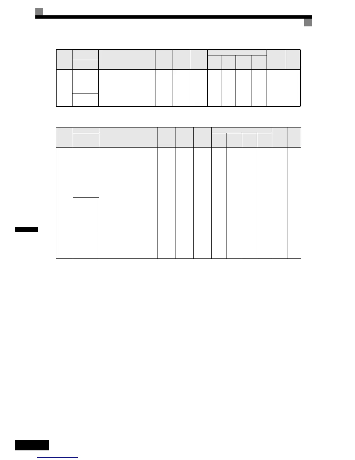
Analog Reference Card: F2
F1-14
PG open-cir-
cuit detec-
tion delay
time
Used to set the PG disconnec-
tion detection time. PGO will
be detected if the detection
time exceeds the set time.
0.0 to
10.0
2.0 s No No A No A 38DH 6-146
PGO Detect
Time
Param-
eter
Number
Name
Description
Setting
Range
Factory
Setting
Change
during
Opera-
tion
Control Methods
MEMO
BUS
Regis-
ter
Page
Display V/f
V/f
with
PG
Open
Loop
Closed
Loop
Vector
F2-01
Bi-polar or
uni-polar
input selec-
tion
If an AI-14B analog reference
card is used this parameter sets
the functions for the input
channels 1 to 3.
0: 3-channel individual, the
AI-14B input channels
replace the analog input ter-
minals A1 to A2 of the
inverter (Channel 1: termi-
nal A1, Channel 2: terminal
A2) and adds a third analog
input with Channel 3.
1: 3-channel addition (Addi-
tion values are the fre-
quency reference)
When b1-01 is set to 1 and
F2-01 is set to 0, the multi-
function digital input function
“Option/Inverter selection” can
not be used.
0 or 1 0 No A A A A 38FH 6-149
AI-14 Input
Sel
Param-
eter
Num-
ber
Name
Description
Setting
Range
Factory
Setting
Change
during
Opera-
tion
Control Methods
MEMO-
BUS
Register
Page
V/f
V/f
with
PG
Open
Loop
Vector
Closed
Loop
Vector
Display

 Loading...


