Through-beam Sensor Heads: FUN Mode Functions
Section 3-8
98
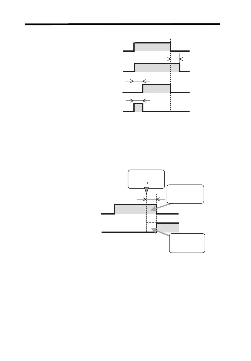
The timing chart is shown below.
Changes for Different Types of Timer and PASS Output (Timer Time: t
0
)
The timer process is applied to the PASS output. This means that an ON-
delay timer of t
0
is applied to the HIGH output when the OFF-delay timer of
t
0
is applied to the PASS output when the measured value changes from
PASS to HIGH as shown in the following figure.
Delay Timer Applied to PASS Output
Example: OFF-delay Timer (t
0
) Going from PASS to HIGH
t
0
t
0
t
0
ON
OFF
ON
OFF
ON
OFF
ON
OFF
Normal output
(Timer disabled)
OFF-delay timer
ON-delay timer
One-shot timer
Measured value
PASS HIGH
t
0
(t
0
)
(t
0
)
OFF-delay timer
ON-delay timer
PASS output
ON
OFF
ON
OFF
HIGH output

 Loading...


