Connections Section 1-4
9
1-4-3 Extension Cables
When extending Sensor Head and Amplifier Unit cables, use the following
special cables (order separately).
• 1-m Cable: ZX-XC1A
• 4-m Cable: ZX-XC4A
• 8-m Cable: ZX-XC8A
• 9-m Cable: ZX-XC9A (for use with Reflective Sensors only)
Connect the Extension Cable between the Connecting Cable and the
Amplifier Unit.
Note: Never use two or more Extension Cables to extend the cable length.
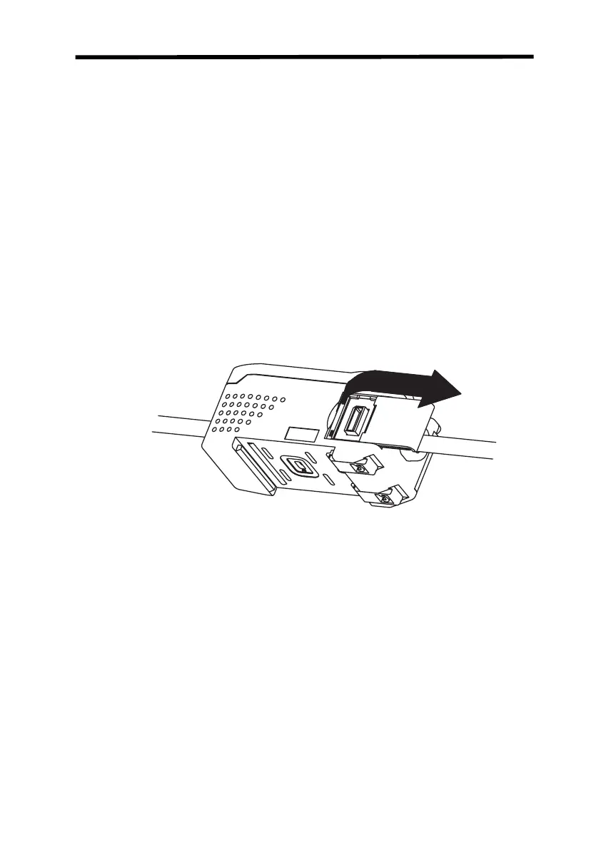
1-4-4 Amplifier Units and Calculating Unit
1. Open the connector covers on the Amplifier Units by lifting and
slide them open.
2. Mount the front section of the Calculating Unit to the DIN Track.
3. Slide the Calculating Unit on the DIN Track until the Calculating
Unit connector connects securely to the connector on the first
Amplifier Unit. The connectors should click into place.

 Loading...


