External Amplifier Unit I/O Section 1-2
5
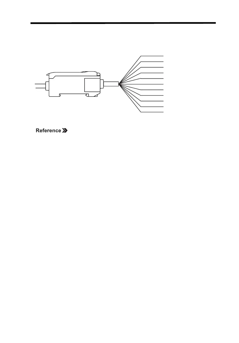
1-2 External Amplifier Unit I/O
The following functions are allocated to the external I/O lines.
Refer to 3-2 Hardware Functions for I/O functions.
Note 1. Use a separate stabilized power supply for the Amplifier Unit, particu-
larly when high resolution is required.
2. Wire the Unit correctly. Incorrect wiring may result in damage to the
Unit. (Do not allow the I/O lines, particularly the linear output, to come
into contact with other lines.)
3. Use the 0-V ground line (blue line) for the power supply and use the
shield wire (linear output ground) together with the linear output (black
line) for linear output. Each of these grounds must be used for the
designed purpose. When not using the linear output, connect the lin-
ear output ground to the 0-V ground line.
12 to 24 VDC
GND (0 V)
HIGH output
PASS output
LOW output
Linear output
Linear output GND
Laser OFF input
Zero reset input
Ti
ming input
Reset input
Brown
Blue
White
Black
Green
Shield
Gray
Pink
Orange
Purple
Red

 Loading...


