2.2.5 Quick Reference Guide
TX1 ships with a Quick Reference Guide that illustrates the drive connections, Status
LED, power button, cable recommendations, and tips for getting started. Keep this
card with TX1 as you familiarize yourself with its operation.
2.3 Reading the status LEDs
On/Off indicator LED: The illuminated power switch is located in the top-left
corner of TX1 and it displays a white LED when the unit is on.
DC In LED: The TP6 power supply cable has a blue LED ring near the end of the
barrel connector that indicates the TX1 power supply is receiving adequate DC input
power.
Activity LED: The multi-color activity LED is located in the lower-right corner of
TX1. It is white when the unit is booting up, blinking white when a power issue is
detected, off when the unit is idle, blue when an operation is in progress, blinking
green when an operation completes successfully, and blinking red when an
operation fails.
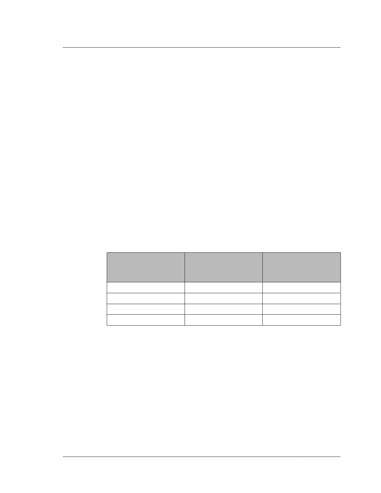
Network Interface LED: The 10 gigabit Ethernet connector is located on the back of
TX1 and it has two LEDs. The table below provides details for interpreting the status
of these network interface LEDs.
Status
Green LED
(Indicates link status and
blinks for activity)
Green/Yellow LED
(Indicates link speed)
No Link Off Off
100 Mbps Link On / Blink Off
1 Gbps Link On / Blink Yellow
10 Gbps Link On / Blink Green
2.4 Interpreting audio feedback
TX1 plays one of two sounds that indicate status at the end of a job. A chime sound
plays for a successful job, and a buzzer sound plays for a failed job. You can change
the volume of the sounds or disable them from the System Settings submenu in the
side navigation menu.
2.3. Reading the status LEDs
ISTX240300-UGD-EN-1
User Guide
21