C200 SOFTWARE
Instruction Manual C200 Part2 A1.doc
optek Danulat GmbH • D-45356 Essen • Germany
page 94
6.2.2 Preparation
a) Switch off the supply and disconnect the conductivity cell(s), temperature compensator(s) and current output(s) from
the analyzer's terminal blocks.
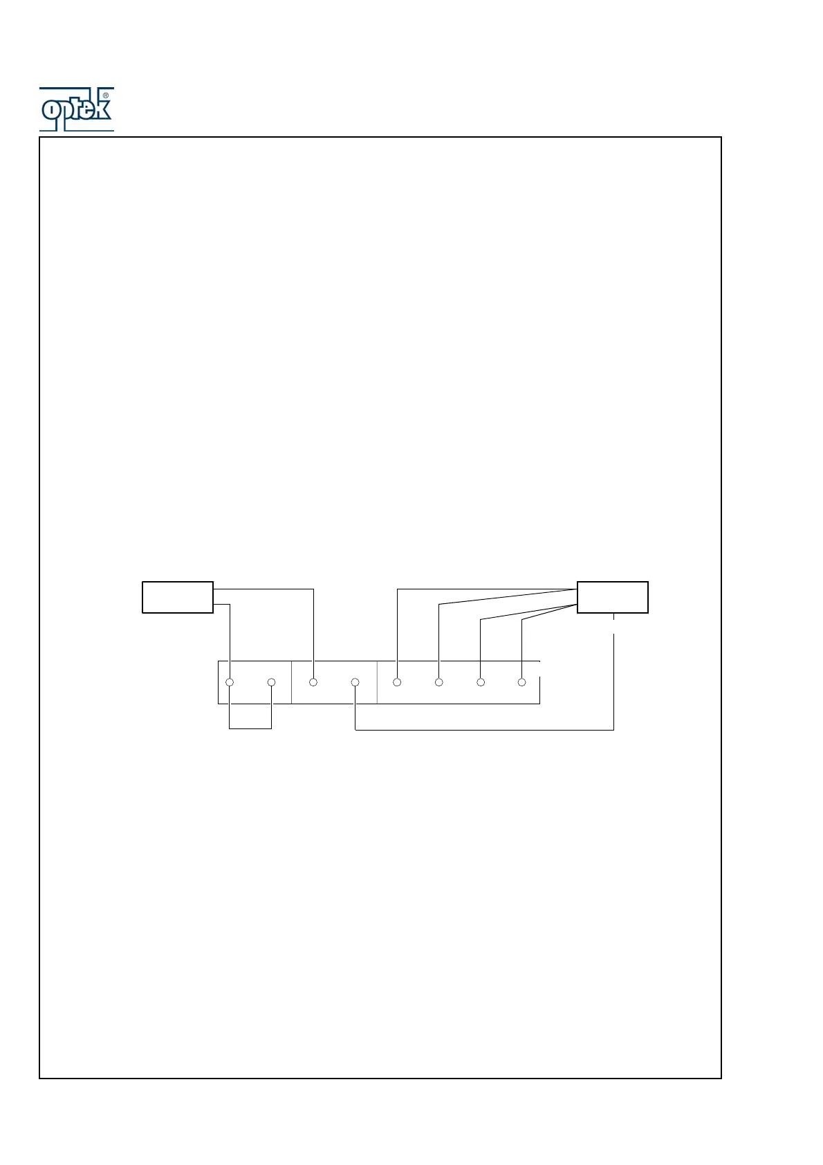
b) Sensor A
1) Link terminals B9 and B10.
2) Connect one terminal of the 0 to 100kΩ decade resistance box to B13 and B14 and the other terminal to B15 and
B16 to simulate the conductivity cell. Connect the decade resistance box earth to B12.
3) Connect the 0 to 10kΩ decade resistance box to B9 and B11 to simulate the Pt1000/3K Balco.
Sensor B (dual input analyzers only)
1) Link terminals B1 and B2.
2) Connect one terminal of the 0 to 100kΩ decade resistance box to B5 and B6 and the other terminal to B7 and B8
to simulate the conductivity cell. Connect the decade resistance box earth to B4.
3) Connect the 0 to 10kΩ decade resistance box to B1 and B3 to simulate the Pt1000/3K Balco.
c) Connect the milliammeter to the analog output terminals.
d) Switch on the supply and allow ten minutes for the circuits to stabilize.
d) Select the FACTORY SETTINGS page and carry out Section 7.2.3.
Terminal link
Conductivity
Cell Simulator
Temperature
Simulator
Earth
B10 B11 B12 B13 B14
B9
Sensor A Terminal Numbers
Sensor B Terminal Numbers
B2 B3 B4 B5 B6
B1
B7 B8
B15
B16