C200 HARDWARE
Instruction Manual C200 Part1 A1.doc
optek Danulat GmbH • D-45356 Essen • Germany
page 17
*
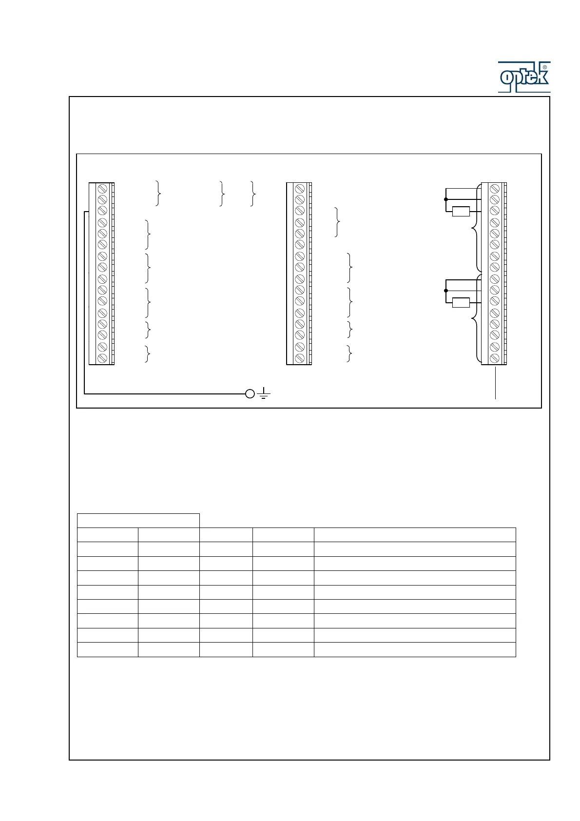
4.3 Sensor wiring
4.3.1 Wiring of conductivity sensors
The wiring of conductivity sensor CF60 to a converter C200 as sensor A and/or B is described in the
following table:
Terminal Block B
Sensor B Sensor A Wire no. Color Function
B1 B9 9 Orange Temperature Compensator Common
B2 B10 10 Red Temperature Compensator 3
rd
lead
B3 B11 11 Blue Temperature Compensator
B4 B12 12 White Sreen
B5 B13 13 Brown Drive -
B6 B14 14 Yellow Sense -
B7 B15 15 Green Sense +
B8 B16 16 Black Drive +
For use with different sensors refer to corresponding instruction manual !
If sensor is equipped with a 2-wire temperature compensator, link terminals B9 and
B10 (and B1 and B2 if dual input analyzer) !
LLine
N Neutral
E Connect supply earth (ground) to stud on case
A4 C
A5 NC Relay 1
A6 NO
A7 C
A8 NC Relay 2
A9 NO
A10 C
A11 NC Relay 3 (see Note below)
A12 NO
A13 +
Analog Output 1
A14 —
A15 +
Analog Output 2
A16 —
Term in a l B lock BTerminal block A
Temperature Compensator
Connections
Common
Third Lead
TC
B1
B2
B3
B4
B5
B6
B7
B8
B9
B10
B11
B12
B13
B14
B15
B16
Common
Third Lead
TC
Temperature Compensator
Connections
Te rm in a l B lock C
(Option Board)
C1 Not Used
C2 Not Used
C3
C4
C5
C6 Not Used
C7 C
C8 NC Relay 4
C9 NO
C10 C
C11 NC Relay 5
C12 NO
C13 +
Analog Output 3
C14 —
C15 +
Analog Output 4
C16 —
Earth (Ground)
Stud on Case
Used for optional
RS485 connections –
refer to IM/PROBUS
85 to 265 V AC + 12
or to
Power
24 V AC – 24V DC
Supplies
Sensor A
Sensor B