C200 HARDWARE
Instruction Manual C200 Part1 A1.doc
optek Danulat GmbH • D-45356 Essen • Germany
page 18
*
4.3.2 Wiring of pH sensors
The converter CONTROL 200 can be connected to either a standard pH input or differential pH input. The
dual input pH is designed for use with pH electrode systems that incorporate a solution earth (ground)
connection to provide low glass impedance and out-of-sample/broken cable warnings.
The wiring of pH sensor PF12 with ABB combination electrodes to a converter C200 as sensor A and/or B is
described in the following tables:
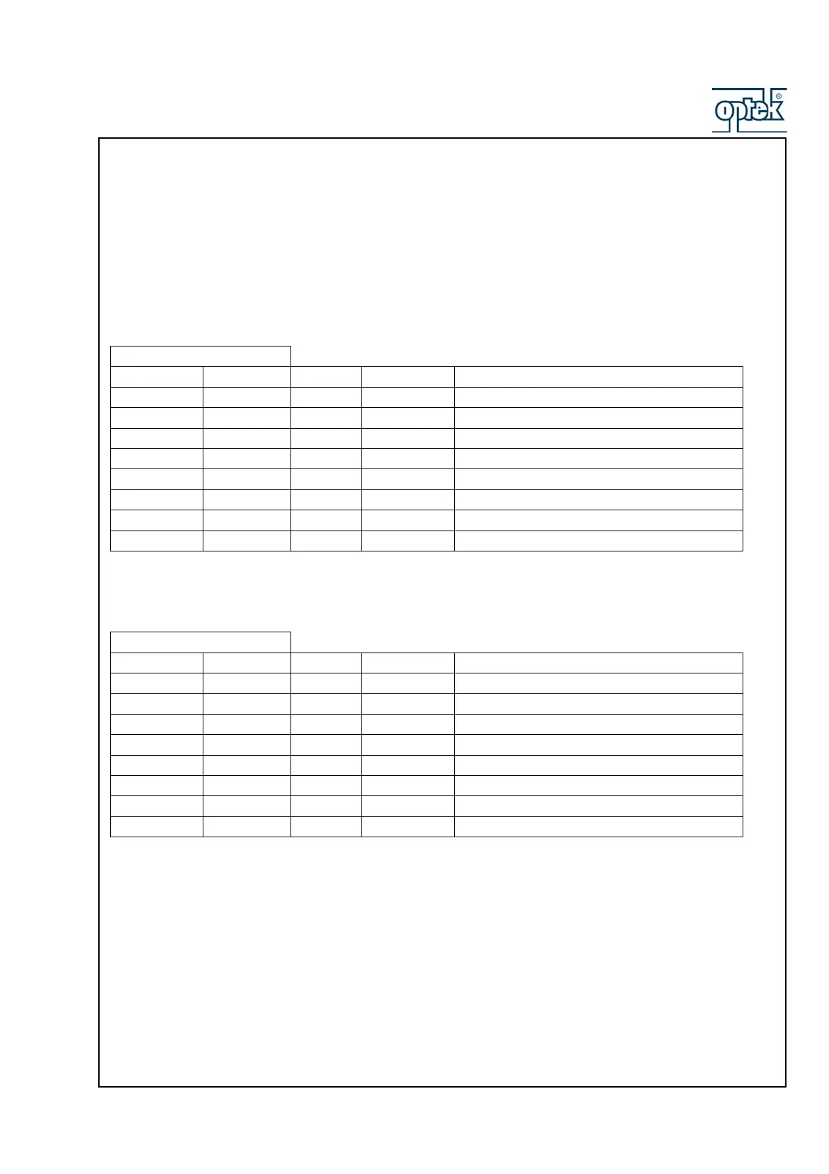
Wiring with solution earth (ground) for inline sensor diagnostic
Terminal Block B
Sensor B Sensor A Wire no. Color Function
B1 B9 1 Grey Temperature Compensator Common
B2 B10 2 White Temperature Compensator 3
rd
lead
B3 B11 3 Green Temperature Compensator
B4 B12 4 Blue Reference
B5 B13 Not used Not used
B6 B14 6 Green/Yellow Solution Earth (Ground)
B7 B15 7 Red Screen/Shield
B8 B16 8 Transparent Glass Electrode
Wiring without solution earth (ground)
Terminal Block B
Sensor B Sensor A Wire no. Color Function
B1 B9 1 Grey Temperature Compensator Common
B2 B10 2 White Temperature Compensator 3
rd
lead
B3 B11 3 Green Temperature Compensator
B4 B12 Not used Not used
B5 B13 Not used Not used
B6 B14 4 Blue Reference
B7 B15 7 Red Screen/Shield
B8 B16 8 Transparent Glass Electrode
For use with different sensors refer to corresponding instruction manual !
If sensor diagnostics are required, ensure that Diff. Input for the relevant sensors is
set to “YES” – see Instruction Manual Control 200, Part 2 - Software !
If sensor is equipped with a 2-wire temperature compensator, link terminals B9 and
B10 (and B1 and B2 if dual input analyzer) !