C200 SOFTWARE
Instruction Manual C200 Part2 A1.doc
optek Danulat GmbH • D-45356 Essen • Germany
page 28
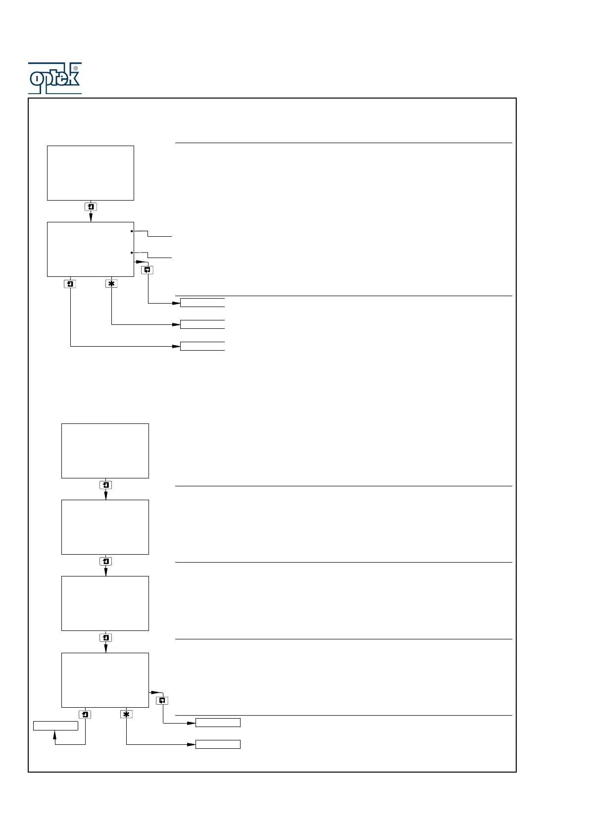
3.2.2 View Outputs
Theoretical Analog Output
There are up to four analog outputs, each showing information for one sensor.
Note. Analog outputs 3 and 4 available only if option board fitted and analog
features enabled – see Section 6.2.3.
Live current output value being retransmitted.
Current output shown as a percentage of full scale for the output range set in
CONFIG. OUPUTS – see Section 5.2.5.
See Section 3.2.3
See Section 4.2.
Advance to analog output 2 (and outputs 3 and 4 if option board fitted
and analog features enabled – see Section 6.1.3).
3.2.3 View Hardware
Sensor A Module
Shows the type of input board fitted to the analyzer for the Sensor A input.
4 Cond – 4-Pole Conductivity
Sensor B Module – Dual input analyzers only
Shows the type of input board fitted to the analyzer for the Sensor B input.
Option Board
Note. Displayed only if the option board is fitted.
Displays the optional features enabled in the Factory Settings page – see Section
6.1.3.
See Section 3.2.4.
See Section 4.2.
50.0
%
Analog Output 1
12.00
mA
VIEW OUTPUTS
-----
VIEW HARDWARE
SENSOR CAL.
Analog Output 2
4 Cond
4 Cond
-----
Sensor A Module
VIEW HARDWARE
-----
Option Board
-----
Sensor B Module
-----
Analog
Pb DP
VIEW SOFTWARE
SENSOR CAL.
VIEW HARDWARE