C200 HARDWARE
Instruction Manual C200 Part1 A1.doc
optek Danulat GmbH • D-45356 Essen • Germany
page 13
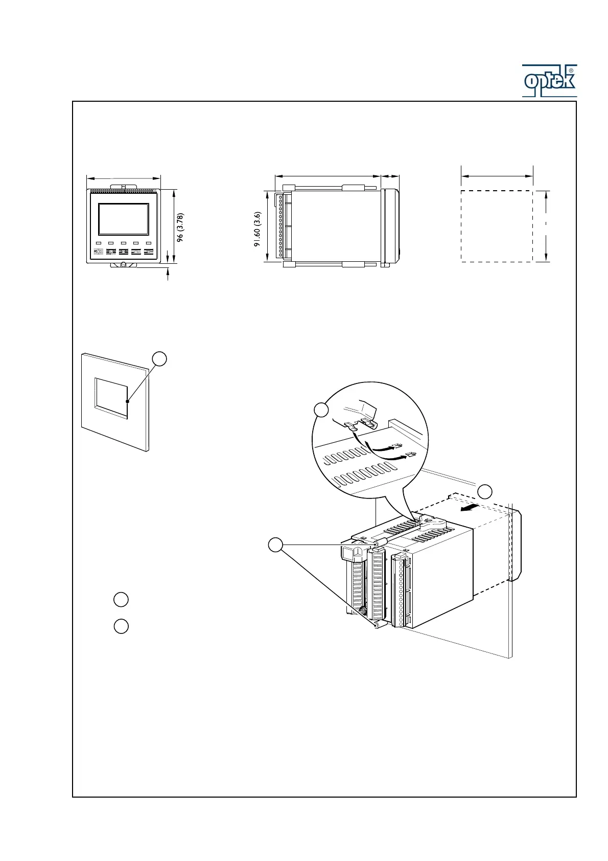
3.3 Dimensions Control 200
Dimensions in mm (in.)
96 (3.78)
5.40 (0.2)
137.50 (5.41)
25
(0.98)
Panel Cut-out
+0.8
–0
92
(3.62 )
+0.03
–0
+0.8
–0
92
(3.62 )
+0.03
–0
3.4 Frontpanel Mounting
Mount in a location free from excessive vibration
Mount away from harmful vapours and/or dripping fluids
Where possible, mount the analyzer at eye level to allow an unrestricted view of the
front panel displays and controls
Insert the instrument
into the panel cut-out
Secure the analyzer by tightening the panel clamp
retaining screws (see
Note
below)
Loosen the retaining
screw on each panel
clamp
Remove the panel clamp and
anchors from the instrument case
Cu
a hole in the panel (see Fi
.6.4fo
dimensions).
Instruments may be close stacked to DIN 43835
1
2
3
4
5
6
Refit the panel clamps to the case, ensuring that the
panel clamp anchors are located correctly in their slots
*