C200 SOFTWARE
Instruction Manual C200 Part2 A1.doc
optek Danulat GmbH • D-45356 Essen • Germany
page 48
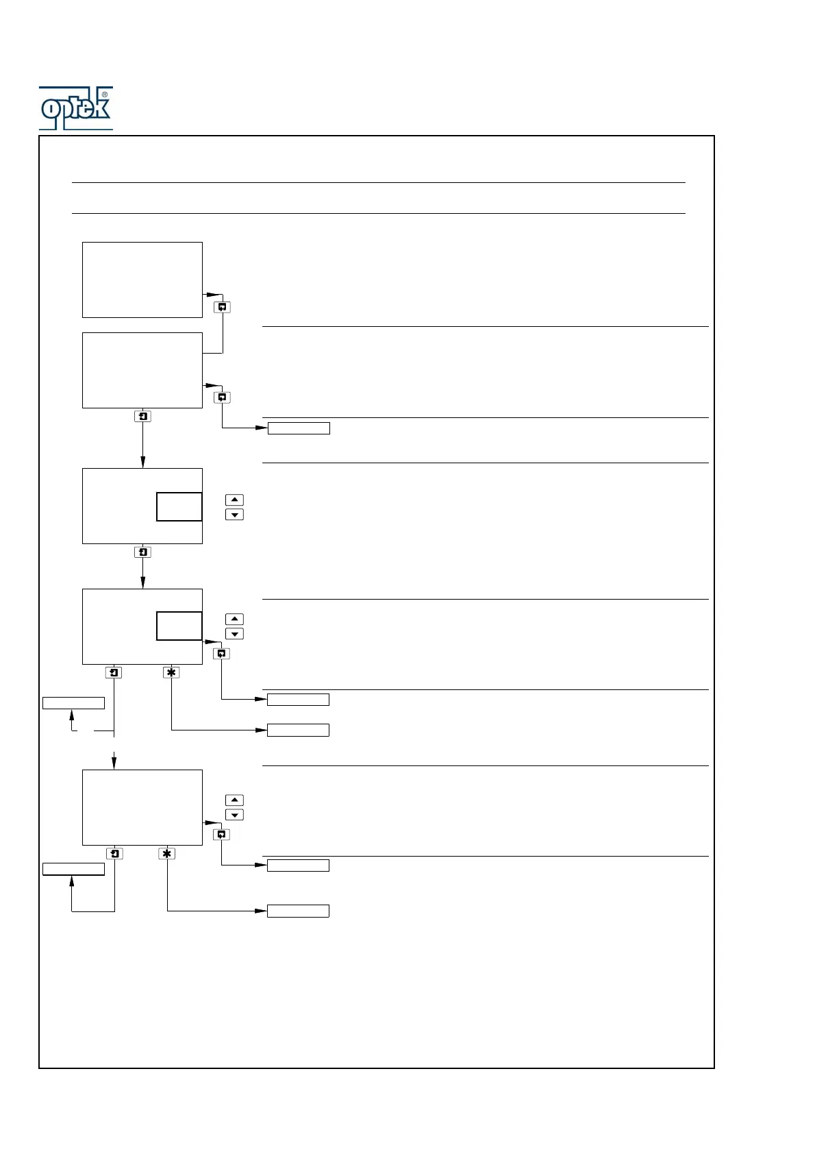
5.1.4 Configure Diagnostics
Note. The Configure Diagnostics function is applicable only if Diff. Input for Sensor A and/or Sensor B is set to
Yes – see Section 5.1.3.
Configure Sensor A
Sensor B configuration (dual input analyzers only) is identical to
Sensor A configuration.
pH Glass Check
Set to On to enable the impedance of the glass electrode circuit to be monitored
in order to provide low glass impedance and out-of-sample/broken cable
warnings.
Note. This frame is displayed only if A: Probe Type is set to pH and A: Electrode
is set to Glass – see Section 5.1.3.
Reference Electrode Check
Set to On to enable the condition of the reference electrode to be monitored in
order to provide:
– an indication of when sensor cleaning or replacement is required
– out-of-sample/broken cable warnings
Sensor B (dual input analyzers only) configuration is identical to
Sensor A configuration.
See Section 5.1.5.
Reference Alarm
Set the impedance value above which the reference alarm is activated.
Sensor B (dual input analyzers only) configuration is identical to
Sensor A configuration.
See Section 5.1.5.
Config. Sensor A
-----
A: pH Glass
-----
A: Ref. Checking
-----
CONFIG. DIAGS
-----
Off
On
Off
On
A: Ref. Alarm
50
kOhm
CONFIG. ALARMS
Config. Sensor A
CONFIG. ALARMS
Config. Sensor B
Config. Sensor B
Config. Sensor B
Config. Sensor A
On
Off