}
T1 T2
MAIN
CONDITION
INITIAL
CONDITION
CRATER-FILL
CONDITION
A
IPM
V
DISPLAY
CHANGE
`
WARNING
IP M
u
}
Sec
J O B N o.
%
Hz
10. OPERATION (continued)
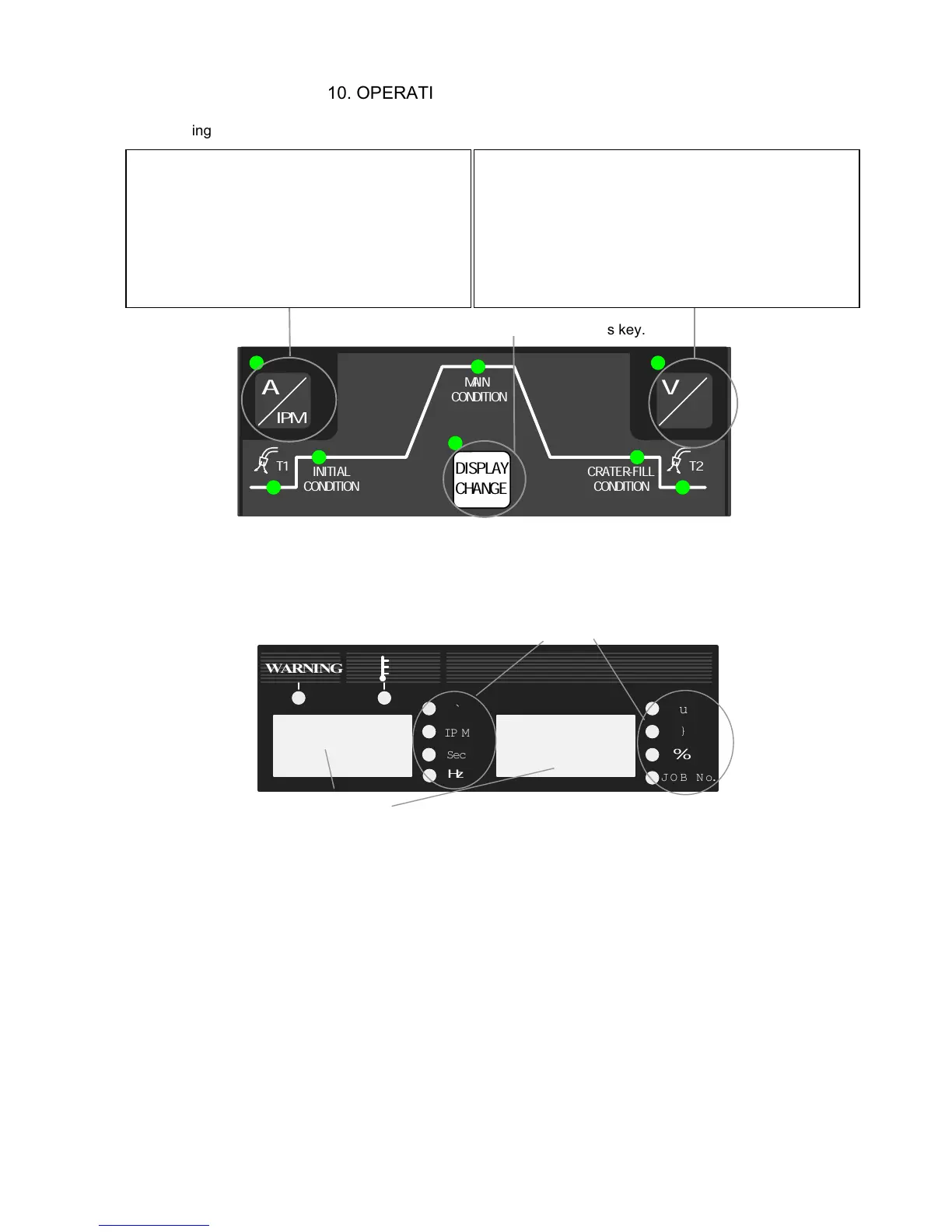
10.1.2 Setting the Parameter
Select a parameter using this key.
[Parameter selector]
Choose a desired parameter using the DISPLAY CHANGE key [8]. Display in the
displays are changed according to the parameters you select and the UNIT lamp of
the parameter lights up.
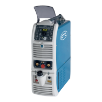
[Parameter displays]
z
When the wire feed speed is displayed, you can not set to the maximum feed speed
using the parameter adjusting knob [6] depending on the welding mode settings
(especially for large diameter). You are only allowed to set the wire feed rate to the
value that can achieve the current setting determined by the rated output current.
z
The values shown in the displays are not the actual data but the setting values of
voltage, current, and wire feed speed. Use the values in the displays as
approximates.
Pressing the key while the A/m/min lamp (located
at the upper left of the A/m/min selector key) is lit
changes over displays of current setting and wire
feed rate. Pressing the A/m/min selector key
while the A/m/min lamp is not lit causes the
A/m/min lamp to light. While the A/m/min lamp is
lit, current can be adjusted using the parameter
adjusting knob [6].
Pressing the key while the V/r lamp (located at the
upper left of the V/r selector key) is lit changes over
displays of current setting and wire feed rate. Pressing
the V/r selector key while the V/r lamp is not lit causes
the V/r lamp to light. While the V/r lamp is lit, current
can be adjusted using the parameter adjusting knob [6].
UNIT lamps
Digital Meter