No. P10355
|62 |
11. APPLIED FUNCTION (continued)
*4 Be careful that no-load voltage (100V or less) is applied to between the terminals during welding.
11. 3 Combining with an Automatic Machine
When combining with an automatic machine, use the 12P/6P terminal block inside the welding
power source, the 10P terminal block inside the wire feeder, and the receptacle for the remote
control or for the wire feeder. Refer to Section 11.2, “External Connection of the Inside
Terminal Block of the Automatic Machine” for the details of the terminal block inside the
welding power source.
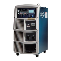
(1) Current/Voltage Settings and Inching Signal
When the analog remote control (optionally supplied) is not in use, resistor R23 for current
setting, resistor R24 for voltage setting, and switch PB for inching, which are all listed in
Section 13.1 “Parts List”, should be used. For setting current/voltage on external voltage, refer
to Section 10.2.1(4), “Selection of Auto/Semi-automatic”.
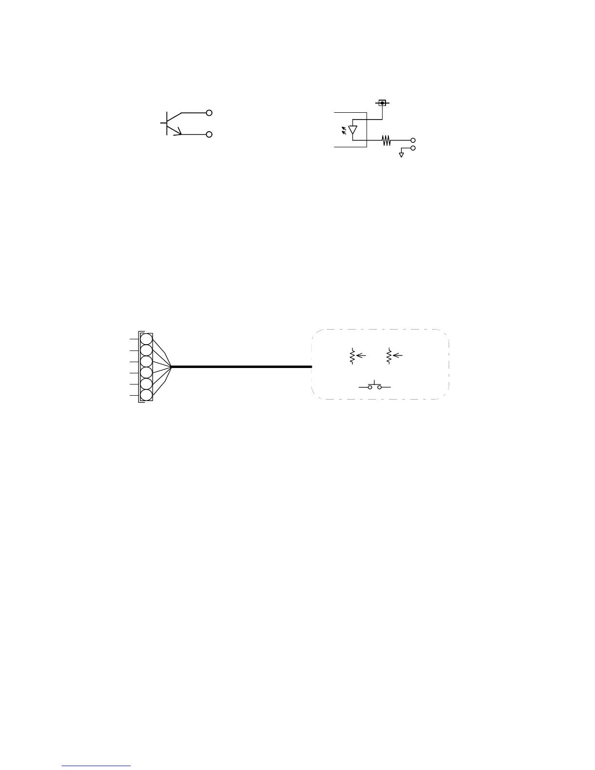
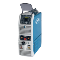
(2) Start Signal
When removing the right-side plate of the wire feeder, you will find a 10P terminal block. See
the figure below. Welding is carried out by the start signal when wiring numbers 306 and 307
are contact input and when the terminals are closed. Welding stops when the terminals are
open.