No. P10355
|
77
|
( )
14. SPECIFICATIONS (continued)
QUICK MANUAL
Refer to Section 10.1, “Basic Settings”and Section 10.2, “Applied Settings”.
Before Using the Welding Power Source
1. Settings of Welding Method
Set a welding method,
wire/ shield gas, then
wire diameter by using
the WELDING METHOD
key, the WIR/GAS
selector keys, and the
WIRE DIA. (mm) key
respectively.
2. Settings of Crater/Arc Spot
Use the CRATER-FILL key to select
OFF/ON(-)/ON( )/ SPOT.
3. Settings of Functions
xFor using INITIAL CURRENT, press the INITIAL
CURR. key to set the function to “ON”.
[ON]: INITIAL CURR. lamp is on.
[OFF]: INITIAL CURR. lamp is off.
xFor controlling voltage in the SYNERG. way, select
“SYNERG.” by pressing the VOLT.CONTROL key.
[SYNERGIC]: VOLT. CONTROL lamp is on.
[INDIVIDUAL]: VOLT. CONTROL lamp is off.
xFor activating a CONSTANT PENETRATION function,
set the function to “ON”.
[ON]: CONTANT PENETRATION lamp is on.
[OFF]: CONSTANT PENETRATION lamp is off.
xFor using a water-cooled torch, select “WATER” by
pressing the TORCH key, then run cooling water.
[WATER]: TORCH lamp is on.
[AIR]: TORCH lamp is off.
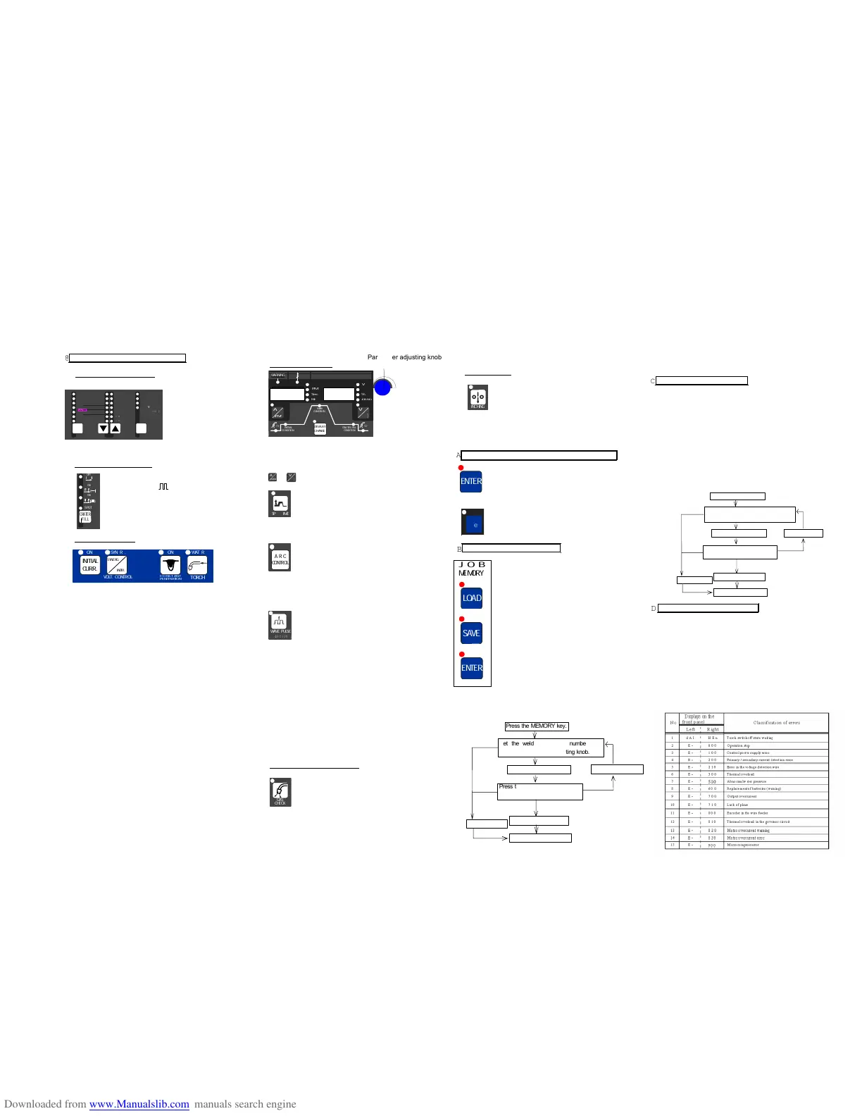
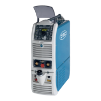
4. Settings of Parameter
Use the DISPLAY CHANGE key to select the parameter
you want to set, then adjust it while turning the parameter
adjusting knob.
When changing the parameter unit in the display, use the
or selector key.
When adjusting SPOT TIME, press the SPOT
TIME key, then set SPOT TIME while turning
the parameter adjusting knob.
[ON]: SPOT TIME lamp is on.
[OFF]: SPOT TIME lamp is off.
To adjust the desired arc characteristic
(HARD/SOFT), after turning on the ARC
CONTROL lamp by pressing the ARC
CONTROL key, set the level of the arc
characteristic.
[ON]: ARC CONTROL lamp is on.
[OFF]: ARC CONTROL lamp is off.
When the welding method is wave pulse, to
obtain the desired bead appearance after
turning on the WAVE PULSE lamp by
pressing the WAVE PULSE key, set the wave
pulse while turning the parameter adjusting
knob.
[ON]: WAVE PULSE lamp is on.
[OFF]: WAVE PULSE lamp is off.
NOTE:
xTurning the parameter adjusting knob clockwise
increases the parameter. To decrease the parameter,
turn the parameter adjusting knob counter-
clockwise.
xThere may be unavailable parameters in some
crater settings and function settings. Refer to
Section 10, “OPERATION” for details.
5. Checking the Rate of Gas Flow
Open the discharge valve of the gas cylinder,
press the GAS CHECK key to check the rate
of gas flow. After performing GAS CHECK,
stop the gas flow by pressing the GAS
CHECK key.
6. Inching the Wire
After pressurizing the wire mounted on the
wire feeder using the pressure roll, feed the
wire up to the end of the torch while using the
INCHING key. When pressing the INCHING
key again, the wire feeding stops.
Now you have completed the preparations that are required to
start welding. Press the torch switch to start welding.
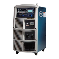
Protecting the Keys and Releasing the Key Protection
xProtecting of the keys
Hold down the ENTER key + the F key at a
time for a few seconds. The F lamp starts
blinking. Blinking of the F lamp means the
welding machine is in the key protection mode.
xReleasing the key protection
Hold down the ENTER key + the F key at a
time for a few seconds. When the F lamp turns
off, the key protection function is released.
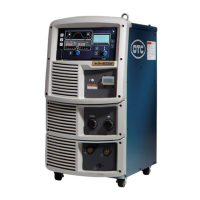
Presetting the Welding Conditions
1) Pressing the SAVE key enters the save
mode. The preset welding condition
number is displayed in the right display
and the welding current is displayed in
the left display.
2) Preset the welding conditions to the
desired numbers 0 - 100 while turning
the parameter adjusting knob. When “---
“ is displayed in the left display, the
number you selected is available. When
“---” is not displayed in the left display,
the number you selected is unavailable.
In this case, select another number.
Otherwise, the welding conditions preset
to the number are erased and
overwritten with the welding conditions
you newly set.
3) Press the ENTER key to check the
parameter preset to the number.
4) When pressing the ENTER key again,
the welding conditions are set.
Loading the Welding Conditions
1) Pressing the LOAD key enter the load mode. The
preset welding condition number is displayed in the
right display and the welding current is displayed in the
left display.
2) Preset the welding conditions to the desired numbers 0
– 100 while turning the parameter adjusting knob.
When “---“ is displayed in the left display, no welding
conditions are preset to the number you selected.
3) Press the ENTER key to check for the parameter
preset to the number.
4) When pressing the ENTER key again, the welding
conditions preset to the welding condition number are
retrieved.
Settings of the (Internal) Functions
1) When holding down the F key for a few seconds, the
function mode is activated. The function number blinks
in the left display, the function status is displayed in
the right display.
2) Set the function number while turning the parameter
adjusting knob.
3) When pressing the F key, the function number lights
up, then the function status blinks.
4) Set the function status while turning the parameter
adjusting knob.
5) To cancel the function mode, hold down the F key for
a few minutes.