ー 153 ー
Installation Instructions Intelligent Controller
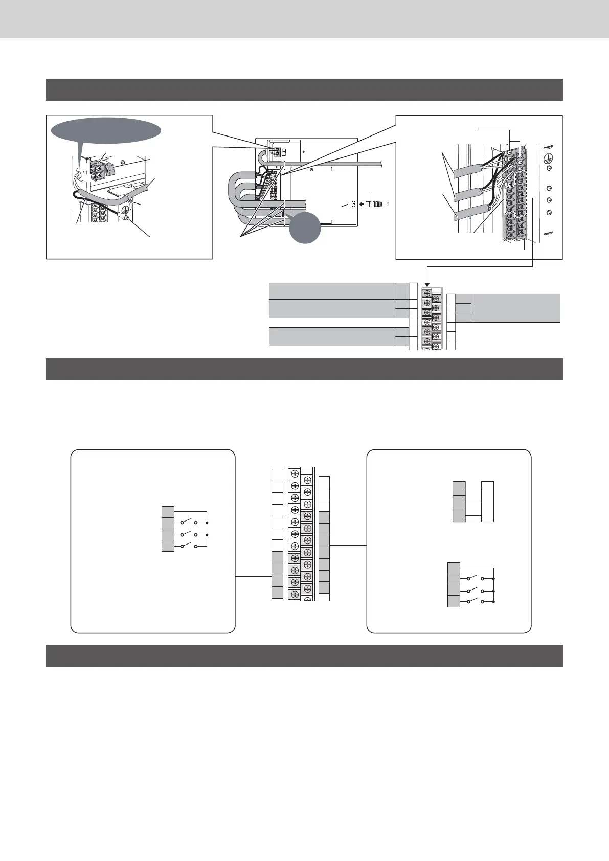
Wiring (continued)
U1
FG*
4
U2
0
1
2
3
4
5
14
15
16
17
18
19
U1
U2
+
-
FG*
4
ON
OFF
ON
OFF
L
N
LAN
Cable
LAN
terminal
Clamper
(supplied)
Power switch
Pass
through the power-in port.
Power supply
wiring
(AC100
~240V)
Earth terminal
board
(Protective earth)
Clamper
(supplied)
Power supply terminal board (TB1)
The earth wiring for
protection should be longer
than the power line (L, N).
Inter-unit
control
wiring
Signal terminal board (TB2)
Use these screws when connecting the shield
wiring to ground (FG
*4
).
External
equipment
connection
terminal
(See “Connecting to External
Equipment”)
Communication
Adaptor control
wiring
Connect to inter-unit control wiring (LINK2)
Connect to inter-unit control wiring (LINK1)
Connect the shield wiring for the inter-
unit control wiring to ground. (FG
*4
) .
Connect the Communication
Adaptor control wiring.
(ADAPT +,-,FG*
4
)
Signal terminal board (TB2) connection
Fix
securely.
Connecting to External Equipment
• Non-voltage contact "a"
• Keep the external I/O wiring lengths of 20 meters or less. If a longer length is needed, use a Communication Adaptor or relay.
• A voltage of DC5 V (approx. 10 mA) is applied to the contact to detect the input signal.
• Do not apply an external voltage to the input terminal.
• The contact allowable voltage and current for the output signal terminal are max. DC30 V and 0.5 A respectively.
Turn on all of the indoor units and the outdoor units.
Turn on the Communication Adaptor (only when
connected), and make the necessary settings.
(See “Installation Instructions” supplied with the
Communication Adaptor.)
Turn on this unit.
Attach the power switch cover to the original position.
• Do not allow the wirings to be caught.
Refer to “Quick Reference” and check the following.
• Check if the clock setting and the number of connected
units are correctly displayed.
• Set the central address.
• Make other necessary settings (unit name, area setting,
distribution setting, etc.).
• Check if the indoor unit, etc. can be operated properly
using this unit, and correct statuses are displayed.
Refer to one of “Service Manual”, “Test Run
Service Manual” and “Technical Data”, and check
the following.
• Make the communication setting with the air conditioner.
• Check and conrm the connection conguration.
Setting and Test Operation
z If the power supply wiring is mistakenly connected
to a terminal board other than the power supply
terminal board, the devices connected to this
controller or this controller will malfunction.
Common (COM1)
Pulse meter input (Pi1)
Pulse meter input (Pi2)
Pulse meter input (Pi3)
Pulse meter input
(Non-voltage contact "a" Pulse)
Equipment side
• Minimum pulse width: 30 msec
or more, or 100 msec or more
(selectable by setting)
• Minimum pulse interval: 1 sec
17
18
19
20
21
22
23
Common (COM2)
External input
*5
(Non-voltage contact "a" Static)
External output
(Non-voltage contact "a" Static)
Digital input
Common (COM3)
Equipment side
Digital input1 (Di1)
Digital input2 (Di2)
Digital input3 (Di3)
• Minimum application load: DC5V 1mA
*5: When performing the demand control,
connect to External input (Di) terminal.
Digital output1 (DO1)
Digital output2 (DO2)
Equipment side
*4: Functional Ground
0
1
2
3
4
5
6
7
8
9
10
11
12
13
14
15
16
17
18
19
20
21
22
23
25
26
7
8
9
10
Signal terminal board (TB2)
TGR-318_ENG.indb 153 2017/04/06 10:44:42
 Loading...