ー 155 ー
Installation Instructions Communication adaptor
S6 S9S8S7D1
D2 UP
DOWN
SET
HOME
CN32
BA
S1
100-240V~
CN1
31
CN2
10
0
19
9
ADAPTER BOARD
N
ON
OFF
POWER
ADAPT
(
RS485
)
DO-COMMON DI-COMMON
DO 1 DO 2
+–
DI 1 DI 2 DI 3
L
10 11 12 13 14 15 16 17 18 19
LINK1
3P2P1P2U1U
0 1 2 3 4 5 6 7 8 9
(
LINK1
–U2
)
LINK2 P-COMMON
U1 U2
(
LINK2
–U2
)
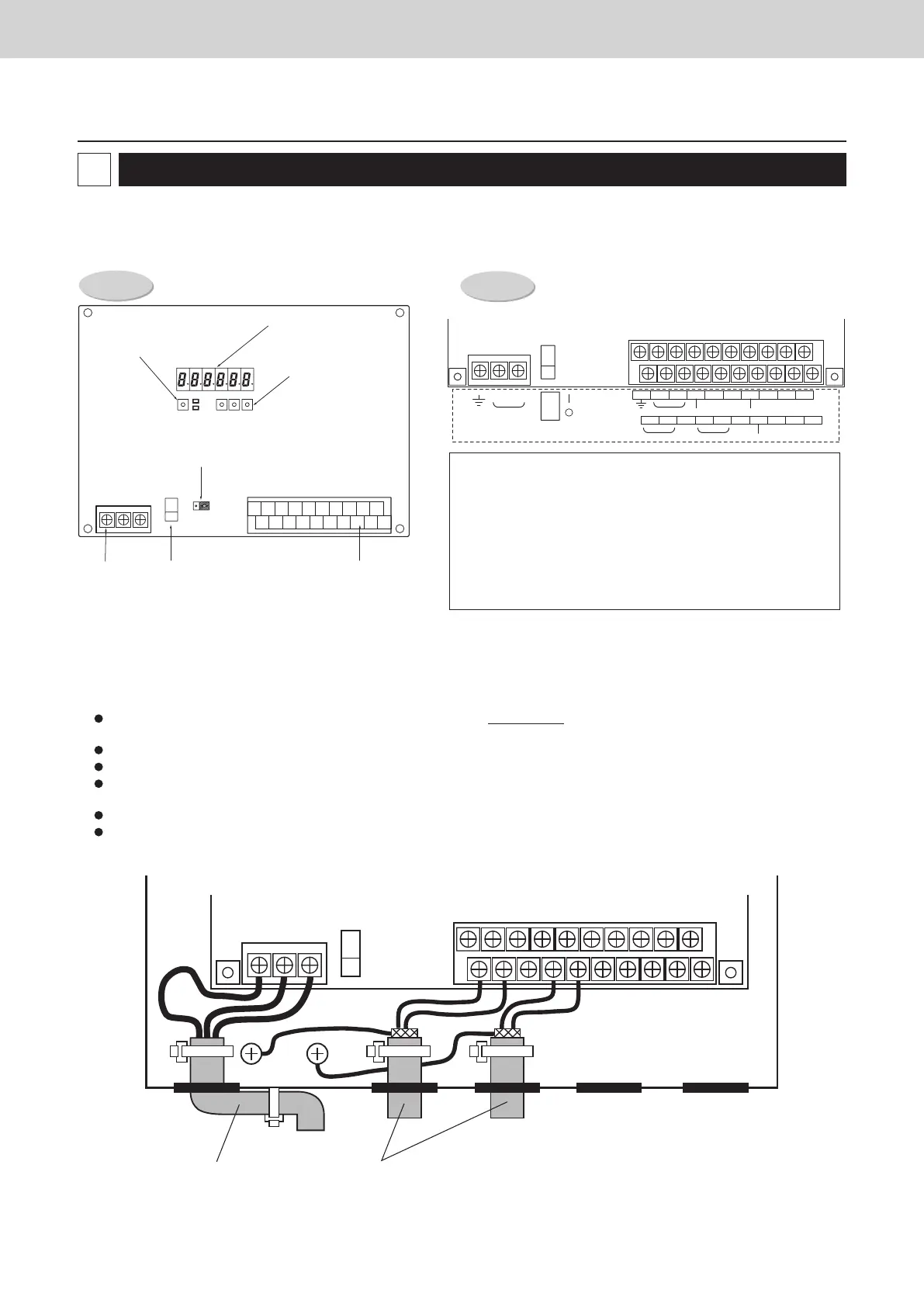
Wiring
Always shut off the power supply (breaker) before installing or uninstalling the Communication Adaptor.
Remove the two screws at the front of the unit and remove the upper case.
Arrangement of the terminal board and switches
Detailed board
illustration
(1) Connecting the power supply
The unit can use AC power sources between 100 and 240 V.
Connect the power supply to terminals 2 (N) and 3 (L) on the power terminal strip CN1. (Connect the AC neutral end to N.)
Connect the ground line securely.
(2) Connecting the communication line
For the Communication Adaptor control wires, use only two-conductor shielded wire with a cross-section between 0.5 and 2.0 mm
2
(MVVS or CPEVS).
Be sure to ground only one end of the shielding.
The overall length of each line should be 1 km or less.
Do not run the communication line through the same conduit as the power supply, use the same cable as the power supply, or run close to
the power supply line (maintain at least 30 cm separation).
Do not run the LINK1 and LINK2 signal lines through the same conduit, use the same cable for wiring, or run them close together.
Use different communication and power cables so they can be differentiated visually.
Detailed terminal
assembly illustration
7-segment LED
Home key
Up, down and
set keys
Terminating resistance plug
for the Communication
Adaptor control wire
Power supply
terminal strip
Power switch Signal terminal strip
(see details at right)
2
ADAPT +/- : Communication Adaptor control wire (RS-485)
LINK 1/2: Inter-unit control wiring (HBS)
P1: Pulse meter inputs (gas flow meter and fuel flow meter) (*)
P2 and P3: Pulse meter input (power flow meter) (*)
DI1: All stop input (*)
DI2: All operation input (*)
DI3: Reserved
DO1: All alarm output (*)
DO2: All operation output (*)
(*) Input/output function when connecting to the Intelligent Controller
100-240V~
Inter-unit control wiring
Power Supply wiring
TGR-318_ENG.indb 155 2017/04/06 10:44:43
 Loading...