ー 160 ー
Installation Instructions Communication adaptor
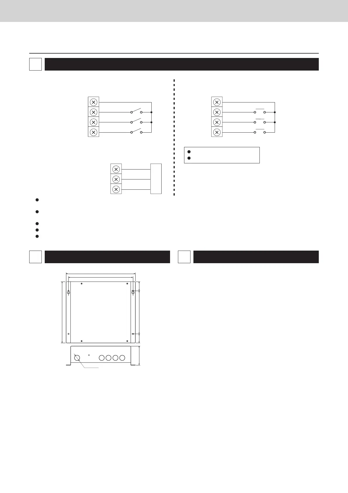
Connecting to external equipment
5
(1) External all input (No-voltage a-contact
static)
DI–COMMON
DI 1
DI 2
DI 3
(2) External all output (No-voltage a-contact
static)
DO–COMMON
DO 1
DO 2
(3) Pulse meter input (No-voltage a-contact
pulse)
P–COMMON
P1
P2
P3
Minimum pulse width: 100 msec
Minimum pulse interval: 1 sec
(* ) Input/output function when connecting to the Intelligent
Controller
Gas flow meter (*)
(fuel flow meter)
Keep the signal input line lengths to 20 meters or less. For distances greater than this, install a standalone Communication Adaptor or use
a relay.
For use in areas that may be susceptible to electrical noise, use a two-conductor shielded cable (with one line grounded), with a cross-
section at least 0.5 mm
2
.
Do not apply external voltages to the input terminals.
About 10 mA of 5 V DC voltage is applied to the contact point for input terminal detection.
The output terminal allowable contact voltage and current are 30 V DC and 0.5 A.
All stop input (*)
All operation input (*)
(Reserved)
(Common output)
(*) All alarm output
(*) All operation output
Equipment
Digital input
Power flow meter 1 (*)
Power flow meter 2 (*)
Outer dimensions
6
Specifications
Rated voltage ........................................ Single phase 100-240V~
Rated frequency ................................... 50/60 Hz
Power consumption .............................. 5.6 W max
Operating temperature ......................... –10 to +50°C
Operating humidity ................................ 20 to 80% (no condensation)
7
Equipment
(mm)
290
ø22.2
256
270
180 383879
TGR-318_ENG.indb 160 2017/04/06 10:44:44
 Loading...