12 Shape object
(1)
(X, Y)
(4)
(5)
(6)
(6)
(2)
(X, Y)
(3)
(3)
(2)
(X, Y)
(5)
(4)
(7)
(7)
(1)
(X, Y)
(3)
(3)
(1)
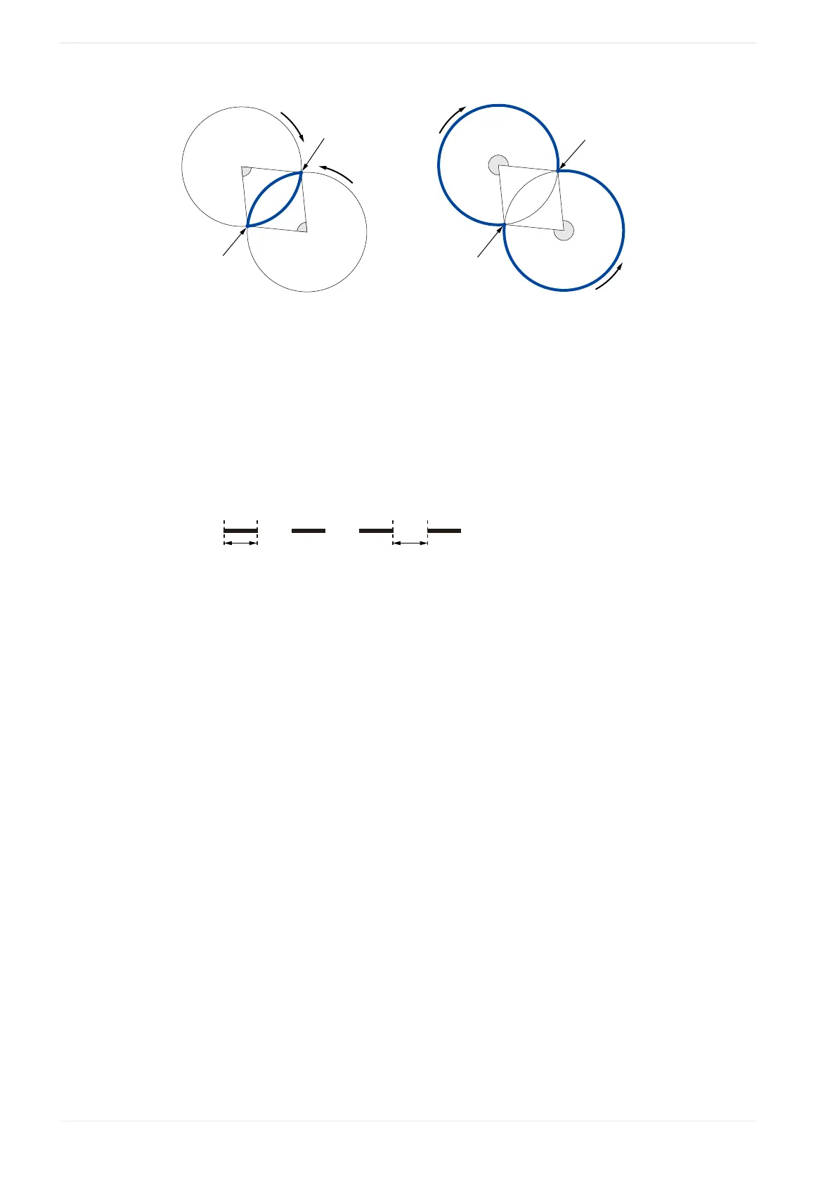
Start point (“X-position of start point [mm] ”, “Y-position of start point [mm]”)
(2)
End point (“X-position of end point [mm] ”, “Y-position of end point [mm] ”)
(3)
“Radius [mm]”
(4)
“Direction” > “CCW”
(5)
“Direction” > “CW”
(6)
“Angle” > “<180°”
(7)
“Angle” > “≥180°”
8. Select “Dash line” to apply dash settings to the arc's stroke.
Specify values for “Dash length [mm] ” and “Gap length [mm] ”.
(2)(1)
(1)
“Dash length [mm] ”
(2)
“Gap length [mm] ”
9. Select “OK”.
The shape object is displayed in the marking image editor and is highlighted in the
object list.
10. To edit the parameters of the shape object, select the object in the object list or in the
marking image editor.
The parameters are displayed in the category below the object list.
Related topics
Create a line (page 135)
Create a circle (page 136)
Add or delete shapes in an existing shape object (page 139)
Position or rotate a shape object (page 139)
General object/object group parameters (page 90)
Set laser correction parameters for a marking object (page 238)
138 ME-NAVIS2-OP-1
 Loading...