Chapter 1 Preparation — About your projector
36 - ENGLISH
Names and functions of the Function Board (optional)
This projector is equipped with Intel
®
Smart Display Module (Intel
®
SDM) specication slot.
Function Board supporting the Intel
®
SDM Small (Intel
®
SDM-S) or the Intel
®
SDM Large (Intel
®
SDM-L)
specication can be installed in the slot.
The terminal names of the optional Function Board with image input terminal to be used in this document is
dened here, and also their operations are explained. Also refer to the Operating Instructions of the Function
Board.
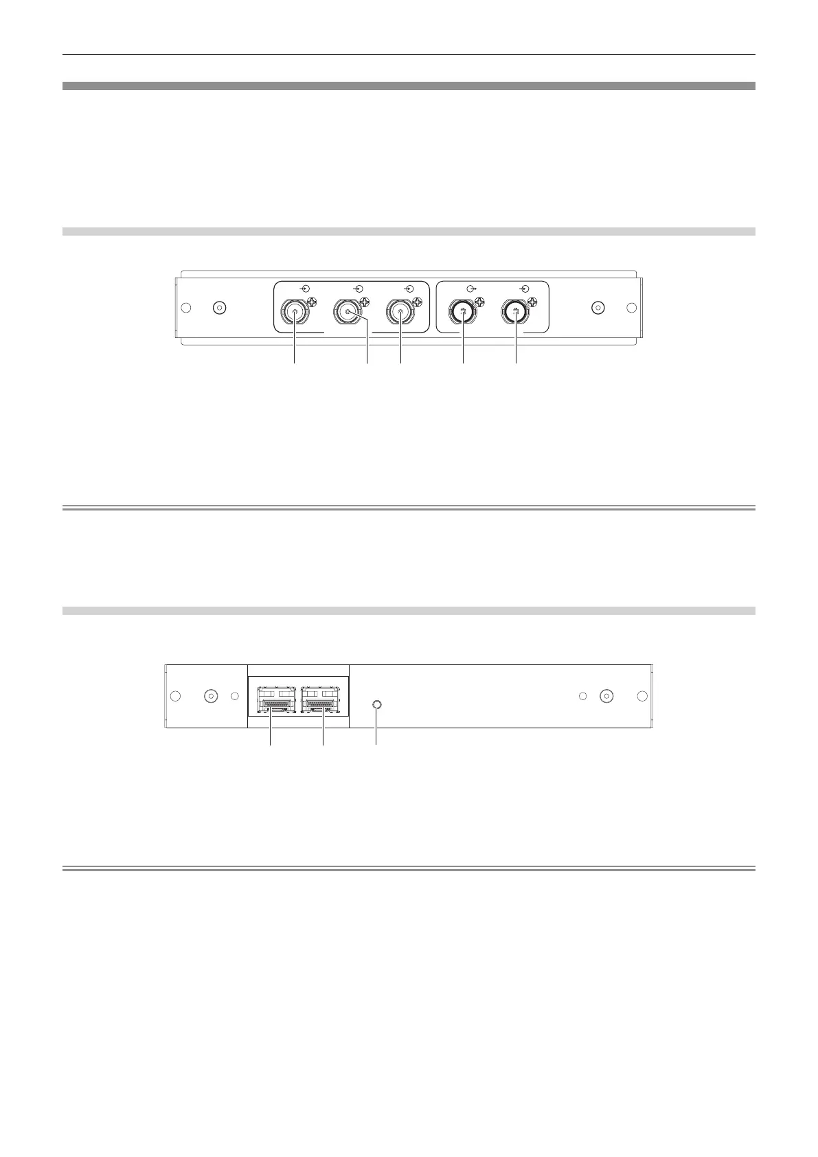
12G-SDI Terminal Board (Model No.: TY-SB01QS)
This board supports the HD-SDI signal, 3G-SDI signal, and 12G-SDI signal.
TY-SB01QS
1 IN
4 IN
3 IN
2 IN
OUT
3G SDI
12G/3G SDI
2 541 3
1 <SDI 4 IN> terminal
This is a terminal to input SDI signal (HD-SDI/3G-SDI).
2 <SDI 3 IN> terminal
This is a terminal to input SDI signal (HD-SDI/3G-SDI).
3 <SDI 2 IN> terminal
This is a terminal to input SDI signal (HD-SDI/3G-SDI).
4 <SDI OUT> terminal
This is an active through terminal to output the SDI signal
(HD-SDI/3G-SDI/12G-SDI) input to the <SDI 1 IN> terminal.
5 <SDI 1 IN> terminal
This is a terminal to input SDI signal (HD-SDI/3G-SDI/12G-SDI).
Note
f The <SDI 2 IN> / <SDI 3 IN> / <SDI 4 IN> terminals are used when the quad link signal is input. These terminals do not support input of
12G-SDI signal.
f When the projector is in standby mode, a signal is not output from the <SDI OUT> terminal.
f This projector is not equipped with an audio function so it is not possible to output audio, but the audio signal input to the <SDI 1 IN>
terminal is output from the <SDI OUT> terminal.
Function Board for 12G-SDI Optical (Model No.: TY-SB01FB)
This board is equipped with two ports that can install the SFP (Small Form-Factor Pluggable)/SFP+ module
(referred to as “SFP module” hereinafter) and supports the HD-SDI signal, 3G-SDI signal, and 12G-SDI signal.
2
3
1
TY-SB01FB
SIGNAL
SDI OPT
12G/3G/HD
1 IN 2 IN
OUT
1 SFP port 1
This is the port to install the SFP module for receiving.
2 SFP port 2
This is the port to install the SFP module for sending and
receiving.
3 Input indicator <SIGNAL>
This is the indicator to indicate the detection state of the video
signal. This is illuminated when input of the video signal is
detected in either or both of the <SDI OPT 1 IN> terminal and
the <SDI OPT 2 IN> terminal.
Note
f The SFP module is an extension module for converting optical signal to electric signal or electric signal to optical signal.
f Prepare the commercially available SFP module and the optical ber cable required for connection according to the usage, video signal to
be input, specication of the external device to be connected, etc.
f Operation of the sending function is restricted depending on the port where the SFP module is installed.
f SFP module compatible with this function board must be correspond to any of the following.
g 12G-SDI/3G-SDI/HD-SDI compatible optical ber SFP module that is compliant with MSA (Multi-Source Agreement)
g Optical ber SFP module that the operation has been veried by Panasonic Connect Co., Ltd.
f To conrm the SFP module that the operation has been veried with the projector, visit the following website.
https://panasonic.net/cns/projector/
Conrmation of operation for SFP module from other manufacturer has been performed with the items set independently by Panasonic
Connect Co., Ltd., and not all the operations are warranted. For operation or performance problems caused by the SFP module, contact the
respective manufacturers.
f The sending function of the SFP module for sending or for sending and receiving will not operate even when it is installed in the SFP port 1.
f In addition to the SFP module for sending and receiving, the SFP module for receiving or for sending can be installed in the SFP port 2.