Chapter 2 Getting Started — Setting up
42 - ENGLISH
Parts for installation (optional)
The projector can be installed on the ceiling by combining the optional Ceiling Mount Bracket (Model No.:
ET-PKD120H (for High Ceilings), ET-PKD120S (for Low Ceilings), ET-PKD130H (for High Ceilings, 6-axis
Adjustment)) and the Ceiling Mount Bracket (Model No.: ET-PKD130B (Projector Mount Bracket)).
f Be sure to use the Ceiling Mount Bracket specied for this projector.
f Refer to the Installation Instructions of the Ceiling Mount Bracket when installing and setting up the projector.
Attention
f To ensure projector performance and security, installation of the Ceiling Mount Bracket must be carried out by your dealer or a qualied
technician.
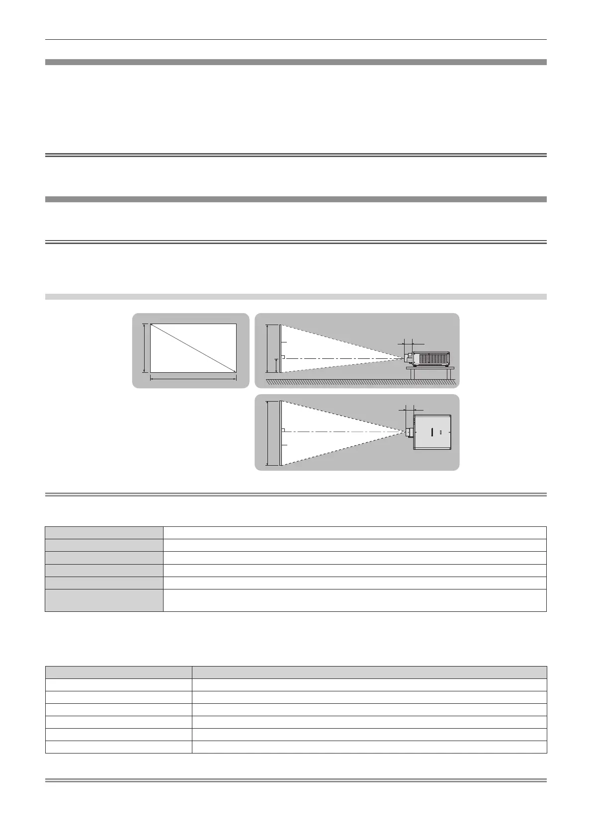
Projected image and throw distance
Install the projector referring to the projected image size, projection distance, etc.
Attention
f Before setting up, read “Precautions for use” (x page 22).
f Do not use the projector and the high-powered laser equipment in the same room. The DLP chips can be damaged if a laser beam hits the
projection lens surface.
Figure of projected image and throw distance
SD
L (LW/LT)
L1
L1
L (LW/LT)
SW SH
H
SH
SW
Note
f This illustration is prepared on the assumption that the projected image size and position have been aligned to t full in the screen.
f This illustration is not in accurate scale.
SH Projected image height
SW Projected image width
SD Projected image size
H Distance from the lens center to the bottom edge of the projected image
L
*1
(LW/LT)
*2
Projection distance (distance from the front end of the projection lens to the screen)
L1
Lens protrusion dimension (distance from the front surface of the projector to the front end of the projection
lens)
*1 For details about calculating the projection distance, refer to “Formula for calculating the projection distance per projection lens” (x page 48).
*2 LW: Minimum projection distance when the Zoom Lens is used
LT: Maximum projection distance when the Zoom Lens is used
(Unit: m)
Projection lens Model No. Lens protrusion dimension (L1) (approximate value)
ET-C1U100 0.384
ET-C1W300 0.155
ET-C1W400 0.149
ET-C1W500 0.144
Standard zoom lens/ET-C1S600 0.110
ET-C1T700 0.160
Note
f For the adjustment range of the projected image position with the lens shift, refer to “Lens shift range” (x page 83).
Projected image
Screen
Screen