Chapter 2 Getting Started — Removing/attaching the projection lens
ENGLISH - 51
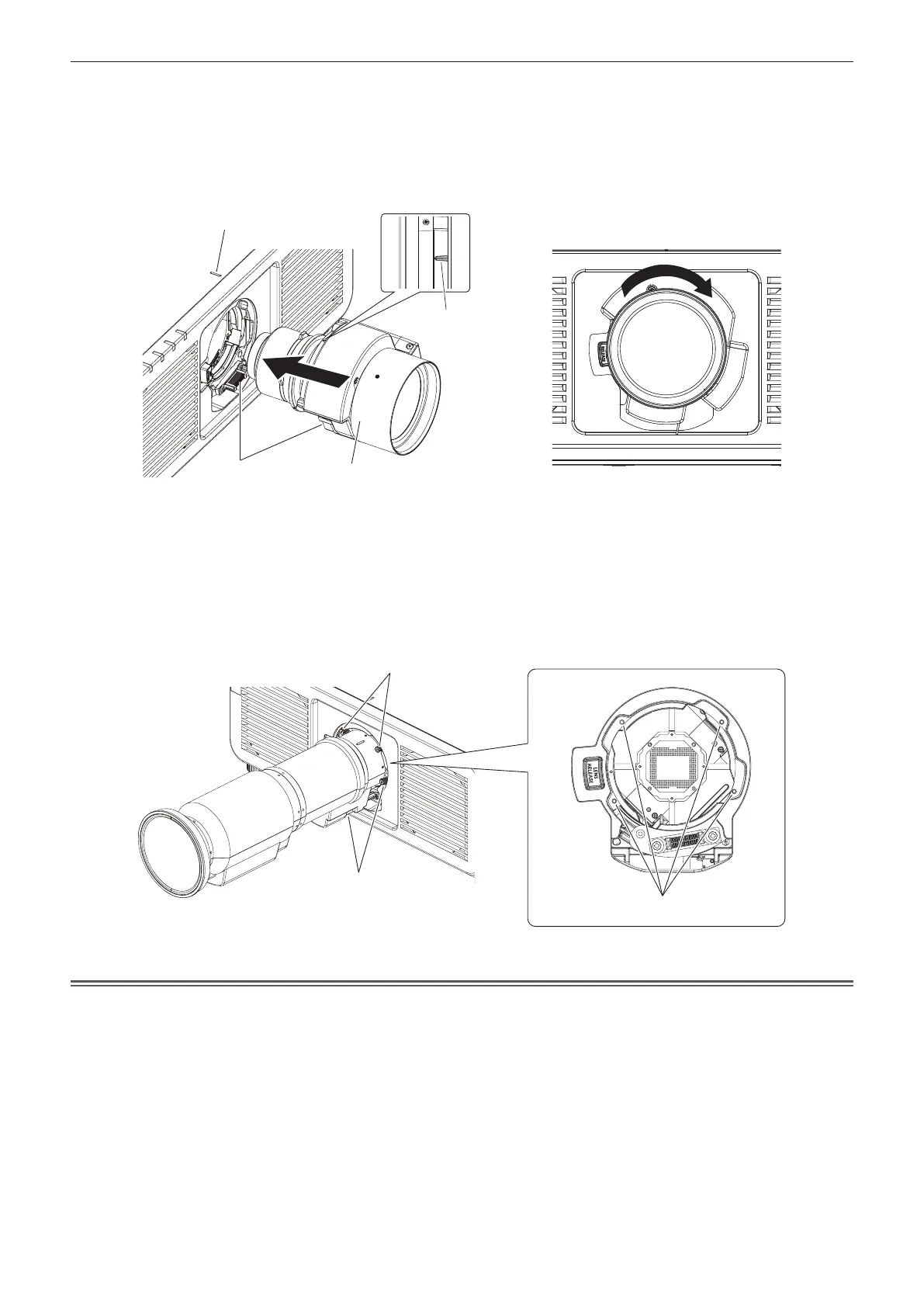
2) Align the protruding mark on the projection lens with the protruding mark of the projector, and insert
the projection lens all the way in. (Fig. 2)
f When inserting the projection lens, be careful not to damage the connector.
3) Turn the projection lens clockwise until it clicks. (Fig. 3)
f Continue to perform Step 4) when attaching the Zoom Lens (Model No.: ET-C1U100).
Fig. 2 Fig. 3
4) Secure the projection lens with the lens fixing screws. (Fig. 4)
(Only for ET-C1U100)
f Tighten the lens xing screws to the four screw holes near the projections lens by using the ball point hex
driver.
g Firmly tighten the lens xing screws in diagonal order while supporting the barrel of the projection lens
from the bottom with your hand.
Fig. 4
Attention
f Turn the projection lens counterclockwise to conrm that it does not come out.
f When attaching the Zoom Lens (Model No.: ET-C1U100), be sure to support the barrel of the projection lens from the bottom with your hand
while tightening the lens xing screws. Failure to do so may cause inadequate tightening of the lens xing screws.
f If the projection lens was replaced, execute the [PROJECTOR SETUP] menu → [LENS] → [LENS CALIBRATION]. (x page 153)
Protruding mark on the projector
Protruding mark
on the projection lens
Projection lens
Connector
Lens xing screws
Lens xing screws
Screw holes
2) While pressing the lens release button(
), turn the projection lens counterclockwise(
) to the end
and remove(
). (Fig. 2)
Fig. 2
Attention
f Store the removed projection lens where it will be free from vibration and impact.
Attaching the projection lens
Attach the projection lens using the following procedure.
Start from Step 2) when the dustproof sponge is already removed.
Prepare a ball point hex driver (diagonal 2.5 mm (3/32")) when attaching the Zoom Lens (Model No.: ET-C1U100).
1) Remove the dustproof sponge. (Fig. 1)
Projection lens
Lens release button
Dustproof sponge
Fig. 1