9-14 Function Parameters
AC10 Inverter
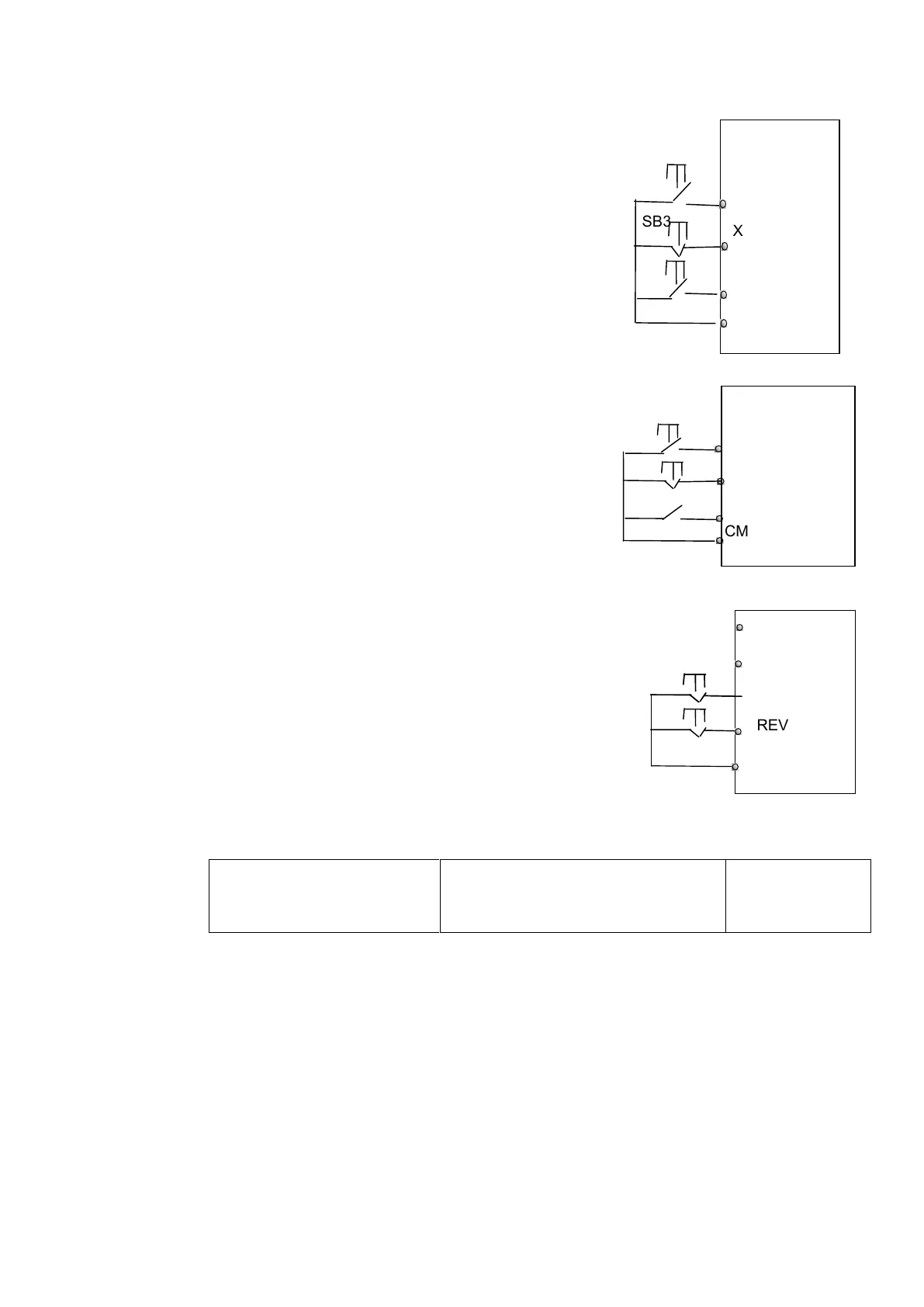
3: Three-line operation mode 1:
In this mode, X terminal is enable terminal, the direction is
controlled by FWD terminal and REV terminal. Pulse
signal is valid.
Stopping commands is enabled by opening X terminal.
SB3: Stop button
SB2: Forward button
SB1: Reverse button
4: Three-line operation mode 2:
In this mode, X terminal is enable terminal, running
command is controlled by FWD terminal. The running
direction is controlled by REV terminal, and stopping
command enable by opening X terminal.
SB1: Running button
SB2: Stop button
K1: direction switch. Open stands for forward running;
close stands for reverse running.
5: Start/stop controlled by direction pulse:
“FWD” terminal—(impulse signal: forward/stop)
“REV” terminal—(impulse signal: reverse/stop)
“CM” terminal—common port
Note: when pulse of SB1 triggers, inverter will run forward.
When the pulse triggers again, inverter will stop running.
When pulse of SB2 triggers, inverter will run reverse. When
the pulse triggers again, inverter will stop running.
F209 Selecting the mode of
stopping the motor
0: stop by deceleration time;
1: free stop(coast stop)
When the stop signal is input, stopping mode is set by this function code:
F209=0: stop by deceleration time
Inverter will decrease output frequency according to setting acceleration/deceleration curve
and decelerating time, after frequency decreases to 0, inverter will stop.
F209=1: free stop
After stop command is valid, inverter will stop output. Motor will free stop by mechanical
inertia.

 Loading...


