9-24 Function Parameters
AC10 Inverter
Note: 1. K4 is multi-stage speed terminal 4, K3 is multi-stage speed terminal 3, K2 is multi-
stage speed terminal 2, K1 is multi-stage speed terminal 1. And 0 stands for OFF, 1 stands for
ON.
0=False, 1=True
F324 Free stop terminal
logic
0: positive logic (valid for low level);
1: negative logic (valid for high level)
F325 External coast
stop terminal logic
0: Free to stop
1: Deceleration to stop
F328 Terminal filtering
times
When multifunctional input terminal is set to free stop (coast stop) terminal (8) or external
coast stop terminal (9), terminal logic level is set by this group of function codes. When
F324=0 and F325=0, positive logic is selected and low level (0V) is true, when F324=1 and
F325=1, negative logic is selected and high level (+24V) is true.
When F326=0.0, watchdog function is disabled.
When F327=0, If the watchdog input (53) does not pulse true, within the time period set by
F326, the inverter will coast to a stop and trip on Err6.
When F327=1, If the time set by F326 elapses without an impulse being registered at the
watchdog input (53), the inverter will decelerate to a stop, then inverter will trip into Err6.
F330 Diagnostics of DIX
terminal
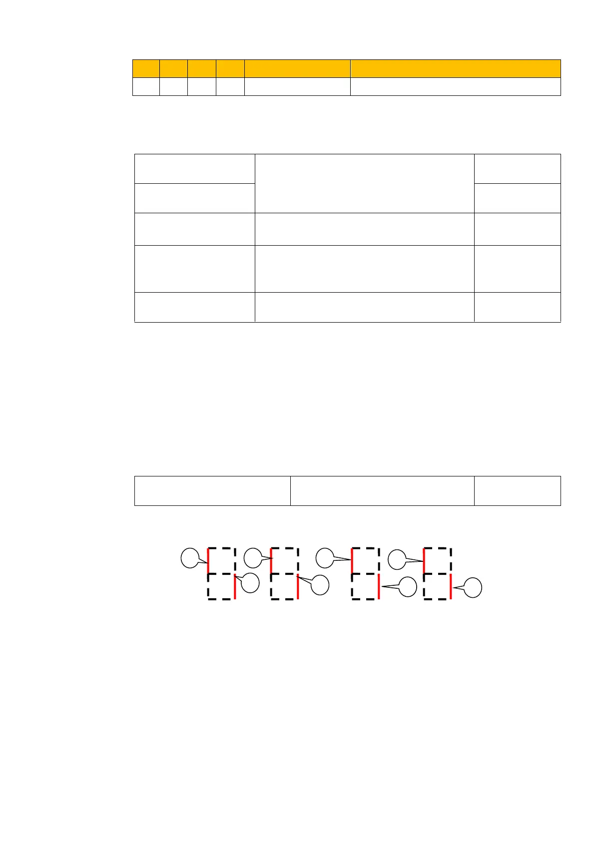
F330 is used to display the diagnostics of DIX terminals.
Please refer to Figure 9-7 about the DIX terminals diagnostics in the first digit.
Figure 9-7 Status of digital input terminal
○1 stands for DI1 valid. ○5 stands for DI5 valid.
○2 stands for DI2 valid. ⑥ stands for DI6 valid.
○3 stands for DI3 valid. ⑦ stands for DI7 valid.
○4 stands for DI4 valid. ⑧ stands for DI8 valid.

 Loading...


