Parker Hannifin Manufacturing Srl user’s manual TPDM
3.4 Power supply
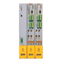
Modules
-
2 axes 3 axes
Control electronics dissipation
Max current (per each axis) A= 1,6
Max total current A= 1,6 3,2 3,2
3.5 Technical characteristics
Peak output current (2 sec)
Shaft power
Continuous service installed load
Modules -
Internal DC capacitors (±20%)
Max continuous module output
current
A 5 10 15 30 4 10 16 16*
Modules -
Internal DC capacitors (±20%)
Max continuous module output
current
A 6 15 16*
(*) the max continuous module current is clamped to 16A